


E6581301
F-7
6
■
■■
■
Connection method
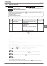
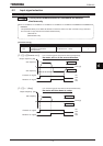
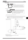
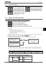
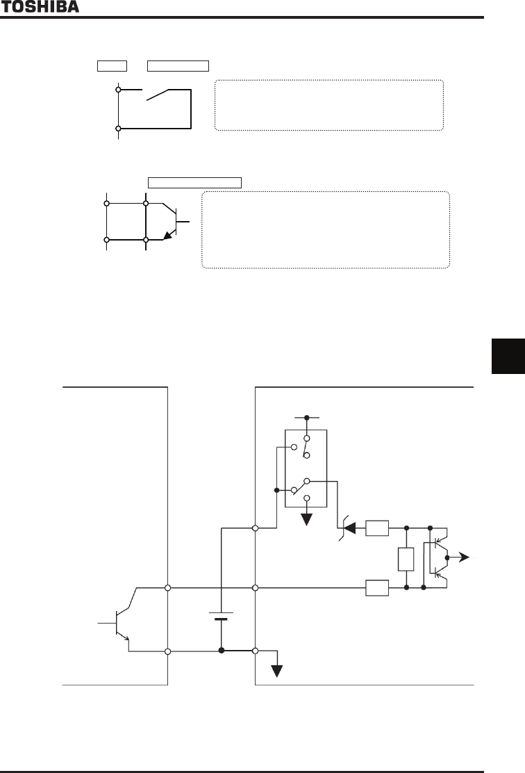
1) a-contact input
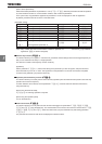
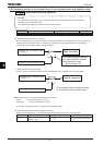
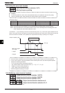
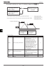
2) Connection with transistor output
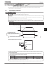
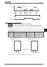
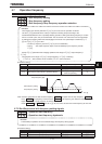
* Interface between programmable controller and inverter
Note: When using a programmable controller with open collector outputs for control, connect it to the P24/PLC
terminal, as shown in the figure below, to prevent the inverter from malfunctioning because of current
flowing in.
Also, be sure to turn the SW1 slide switch to the PLC position.
Programmable controller
PLC
+24V
power
supply
PLC
SW1
+24V
F~S4
CC
P24/PLC
Inverter
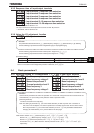
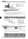
3) Sink logic/source logic input
Sink logic/source logic (input/output terminal logic) switching is possible.
For details, refer to Section 2.3.2.
Ŭ
This function is activated when the input terminal and
CC (common) are short-circuited. Use this function to
specify forward/reverse run or a preset speed operation.
CC
Input
terminal
Inverter a-contact switch
Sink setting
Ŭ
Operation can be controlled by connecting the input and CC
(common) terminals to the output (no-contacts switch) of
the programmable controller. Use this function to specify
forward/reverse run or a preset speed operation. Use a
transistor that operates at 24Vdc/5mA.
CC
Input
terminal
Inverter Programmable controller