


E6581301
F-83
6
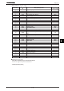
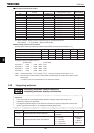
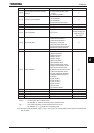
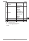
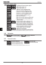
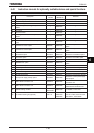
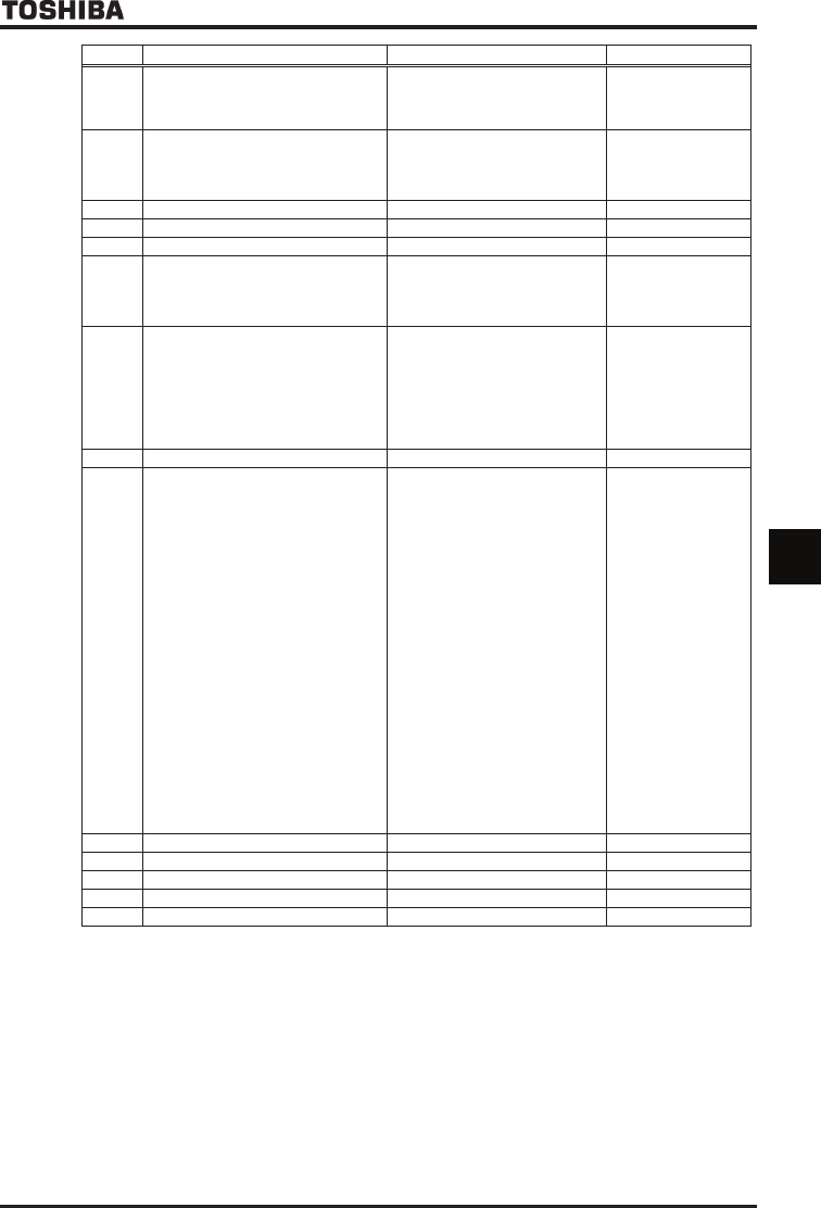
Title Function Adjustment range Default setting
H
Communication1 time-out condition
selection
:Disconnection detection
:When communication mode
enable
:1+Driving operation
H
Frequency point selection
:Disabled
:2-wire RS485
:4-wire RS485
:Communication add option
H
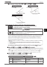
Point 1 setting ~ %
H
Point 1 frequency ~HJ Hz
H
Point 2 setting ~ %
H
Point 2 frequency ~HJ Hz
Inverter with a model
number ending with
-WN, HN:
-WP:
H
Block write data 1
:Disabled
:Command information 1
:Command information 2
:Frequency command
:Terminal board output data
:Communication analog output
:Rotational speed instruction
H
Block write data 2 Ditto
H
Block read data 1
:Deselect
:Status information
:Output frequency
:Output current
:Output voltage
:Alarm information
:PID feedback value
:Input terminal board monitor
:Output terminal board monitor
:VI/II terminal board monitor
:RR/S4 terminal board monitor
:RX terminal board monitor
:Input voltage (DC detection)
:Speed feedback frequency
:Torque
:MY monitor 1
:MY monitor 2
:MY monitor 3
:MY monitor 4
:Free notes
:Rotational speed
H
Block read data 2 Ditto
H
Block read data 3 Ditto
H
Block read data 4 Ditto
H
Block read data 5 Ditto
H
Free notes ~HHHH
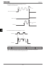
* : No action ... No action is taken even if a timeout occurs.
Alarm ......... An alarm goes off if a timeout occurs.
The message “V” blinks at the left end of the operation panel.
Trip ............ The inverter trips when a communication time-over occurs.
The message “GTT” blinks on the operation panel.
Note: Changes to the parameters H, H and H do not take effect until the power is turned off and
then on again.