


E6581301
B-14
2
■
■■
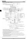
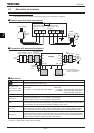
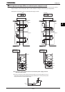
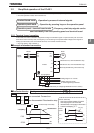
■ Sink logic/source logic (When inverter's internal power supply is used)
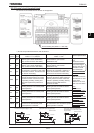
Current flowing out turns control input terminals on. These are called sink logic terminals.
The method generally used in Europe is source logic in which current flowing into the input terminal turns it on.
Sink logic terminals and source logic terminals are sometimes referred to as negative logic terminals and positive
logic terminals, respectively.
Each logic is supplied with power from either the inverter's internal power supply or an external power supply, and its
connections vary depending on the power supply used.
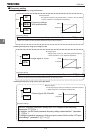
<Examples of connections when the inverter's internal power supply is used>
Source logic
Sink logic
CC
OUT1
P24/PLC
F
Common
Common
Output
Input
Input
24V
DC
Output
F
CC
Common
Output
Input
24V
DC
Output
NO
24V
DC
CC
NO
OUT1
P24/PLC
24V
DC
Input
Common
Inverter
Programmable
controller
Inverter
Programmable
controller
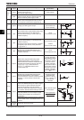
P24/PLC
F
R
ST
CC
OUT1
OUT2
NO
CC
RY
RY
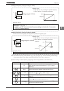
Inverter
P24/PLC
F
R
ST
CC
OUT1
OUT2
NO
RY
RY
Inverter
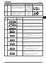
SW1
INT
SW1
INT/P
LC
SINK
SOURCE
P24/PLC
*1
*1:Be sure to short across NO-CC