


E6581301
I-8
9
9.2 Measures to be taken to satisfy the UL/CSA standards
All VF-AS1 series inverters are certified by UL and CSA, and have nameplates with UL and CSA markings.
9.2.1 Caution in installing the inverter
A UL certificate was granted on the assumption that the inverter would be installed in a cabinet. Therefore, install the
inverter in a cabinet and if necessary, take measures to maintain the ambient temperature (temperature in the
cabinet) within the specified temperature range.
For models designed for 15kW motors or smaller, if the cover on the top of the inverter is removed, the ambient
temperature can rise to 50°C in some cases, although the maximum allowable ambient temperature is 40°C.
Incidentally, models (with no cover on the top) designed for 18.5 kW motors or larger can be used at ambient
temperatures of up to 50°C.
9.2.2 Caution in wiring and rated current
Use the UL conformed cables (Rating 75 °C or more, Use the copper conductors only.) to the main circuit terminals
(R/L1, S/L2, T/L3, U/T1, V/T2, W/T3). For FLA, FLB and FLC terminals, the round solderless terminal “V1.25-3” has
to be used with UL-certified electric wire.
For instruction in the United States, Integral solid state short circuit protection does not provide branch circuit
protection. Branch circuit protection must be provided in accordance with the National Electrical Code and any
additional local codes.
For instruction in the Canada, Integral solid state short circuit protection does not provide branch circuit protection.
Branch circuit protection must be provided in accordance with the Canadian Electrical Code and any additional local
codes.
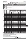
For recommended electric wire sizes, see Tables 5.
UL-certified rated output current is not the same as inverter unit rated current. Refer to Table 5.
9.2.3 Caution as to peripheral devices
Use the UL listed fuses at connecting to power supply.
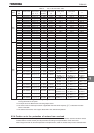
The UL certification test on this inverter was conducted under the AIC* conditions shown in Table 4 (*: current that
flows in the event of a short-circuit in the power supply). Note that AIC currents vary depending on the capacity of the
motor used.
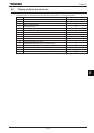
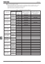
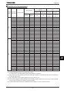
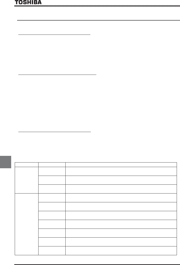
Table 4 Power supply short-circuit current and maximum input voltage
Input voltage Drive motor Power supply short-circuit and maximum input voltage
240V
0.4kW
Suitable For Use On A Circuit Capable Of Delivering Not More Than 5,000A rms
Symmetrical Amperes, 240 Volts Maximum When Protected by CC Class Fuses.
0.75kW to 37kW
Suitable For Use On A Circuit Capable Of Delivering Not More Than 5,000A rms
Symmetrical Amperes, 240 Volts Maximum When Protected by J Class Fuses.
45kW and over
Suitable For Use On A Circuit Capable Of Delivering Not More Than 10,000A rms
Symmetrical Amperes, 240 Volts Maximum When Protected by J Class Fuses.
480V
0.75kW to 1.5kW
Suitable For Use On A Circuit Capable Of Delivering Not More Than 5,000A rms
Symmetrical Amperes, 480 Volts Maximum When Protected by CC Class Fuses.
2.2kW to 37kW
Suitable For Use On A Circuit Capable Of Delivering Not More Than 5,000A rms
Symmetrical Amperes, 480 Volts Maximum When Protected by J Class Fuses.
45kW to 132kW
Suitable For Use On A Circuit Capable Of Delivering Not More Than 10,000A rms
Symmetrical Amperes, 480 Volts Maximum When Protected by J Class Fuses.
160kW to 220kW
Suitable For Use On A Circuit Capable Of Delivering Not More Than 18,000A rms
Symmetrical Amperes, 480 Volts Maximum When Protected by J Class Fuses.
280kW
Suitable For Use On A Circuit Capable Of Delivering Not More Than 30,000A rms
Symmetrical Amperes, 480 Volts Maximum When Protected by T Class Fuses.
355kW to 400kW
Suitable For Use On A Circuit Capable Of Delivering Not More Than 30,000A rms
Symmetrical Amperes, 480 Volts Maximum When Protected by J Class Fuses.
500kW
Suitable For Use On A Circuit Capable Of Delivering Not More Than 42,000A rms
Symmetrical Amperes, 480 Volts Maximum When Protected by J Class Fuses.