


E6581301
F-71
6
6.35 Adjustment parameters
6.35.1 Pulse train output for meters
H
HH
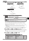
H : Logic output/pulse output selection (OUT1)
H
HH
H : Pulse output function selection
H
HH
H : Selection of number of pulses
•
••
• Function
Pulse trains can be sent out through the OUT1-CC output terminals.
To do so, it is necessary to select a pulse output mode and specify the number of pulses.
This function output the pulse is based on
H
setting when each selection is suitable for the fixed
output 1 level (refer to selection 5.16).
Set the SW4 to pulse output (PULS).
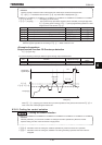
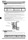
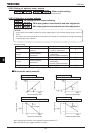
Ex.) When operations frequencies (0 to 60Hz) are put out by means of 0 to 10kHz
HJ=, H=, H=, H=
The pulse will change between 0 and 10kHz according to the operations frequencies between 0 and 60Hz.
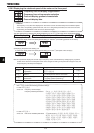
See the circuit diagram shown at the bottom of page B-15.
Title Function Adjustment range Default setting
H
Logic output/pulse output selection
(OUT1)
:Logic output
:Pulse output
H Pulse output function selection
:Output frequency
:Frequency command value
:Output current
:Input voltage (DC detection)
:Output voltage
:Compensated frequency
:Speed feedback(realtime value)
:Speed feedback (1-second filter)
:Torque
:Torque command
:Torque current
:Exiting current
:PID feedback value
:Motor overload factor (OL2 data)
:Inverter overload factor (OL1 data)
:Regenerative braking resistance
overload factor (OLr data)
:Regenerative braking resistor load
factor (% ED)
:Input power
:Output power
:Optional AI2 input
:RR/S4 input
:VI/II input
:RX input
:Optional AI1 input
:FM output
:AM output
:Fixed output 1
:Communication data output
:Fixed output 2
:Fixed output 3
:Cumulative input power
:Cumulative output power
:My function monitor 1
:My function monitor 2
:My function monitor 3
:My function monitor 4
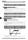
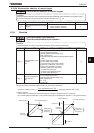
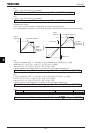
H Selection of number of pulses .~. kHz
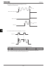
Note: The pulse length is fixed. Therefore, the duty is variable.