


E6581301
F-82
6
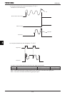
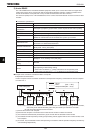
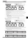
1) 2-wire RS485
The 2-wire RS485 device on the operation panel and the 4-wire RS485 device on the control circuit terminal
block are intended for data communications between inverters. To use an optional part for the RS485 device, it
should be connected to the communication connector (RJ45) on the operation panel. Through the 2-wire RS485
device and a USB device (optional), the inverter can be linked to a computer.
ŬHere are the parts optionally available for the 2-wire RS485 device.
• Optional USB-to-Serial conversion unit (Model: USB001Z)
Inverter-to-RS485/USB device interconnect cable (Model: CAB0011 (1m), CAB0013 (3m), CAB0015 (5m))
RS485/USB device-to-computer interconnect cable. Use a commercially available USB1.1 or 2.0 cable. (Type:
A-B, Cablelength: 0.25~1.5m)
• Optional LED Remote Keypad (Model: RKP002Z)
Communication cable (Model:CAB0011 (1m), CAB0013 (3m), CAB0015 (5m))
• Optional LCD Remote Keypad (Model: RKP004Z)
LCD special cable (Model:CAB0071 (1m), CAB0073 (3m), CAB0075 (5m), CAB00710 (10m))
Note: Do not connect the cable (CAB0011, 0013 or 0015) from the communication device to the optional LCD
Remote Keypad. Or the inverter or the optinol LCD Remote Keypad could be damaged.
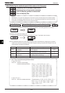
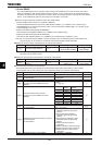
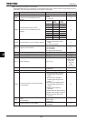
■ Setting for issuing run/stop commands from an external control device
Title Function Adjustment range Default setting Example of setting
EOQF Command mode selection ~
(Terminal input enabled)
(2-wire RS485)
Note: When parameter H (setting for communications between inverters) is used, the setting EOQF=
cannot be used for slave inverters.
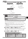
■ Setting for issuing speed commands from an external control device
Title Function Adjustment range Default setting Example of setting
HOQF
Frequency setting mode
selection 1
~
(RR/S4 input)
(2-wire RS485)
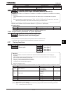
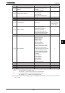
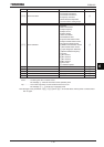
■ Communication parameters (2-wire RS485)
These parameters allow you to change the communication speed, parity check setting, inverter number,
communication error trip timer setting, etc. from the operation panel or an external control device.
Title Function Adjustment range
Default setting
H
Communication speed (2
-
wire RS485)
:9600
bps,
:19200
bp
s,
:38400
bps
H
Parity
(2-wire RS485)
:Non parity
,
:Even parity
:Odd parity
H
Inverter number (common)
~
H
Communications time
-
out time
(common to 2-wire RS485 and 4-wire
RS485)
:OFF
~ sec.
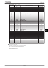
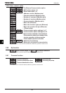
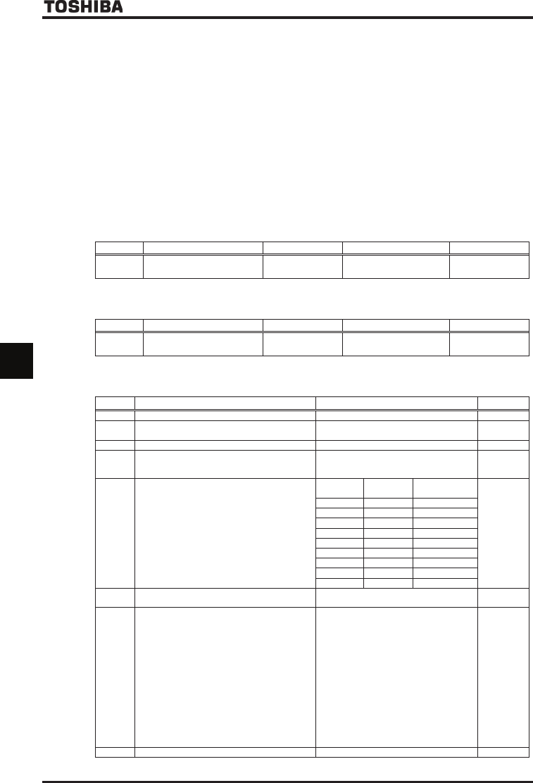
H
Communications time-out action *
(common to 2-wire RS485 and 4-wire
RS485)
Setting
2
-
wire
RS485
4
-
wire
RS485
No action
No action
Alarm
No action
Trip
No action
No action
Alarm
Alarm
Alarm
Trip
Alarm
No action
Trip
Alarm
Trip
Tri
p
Trip
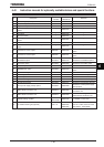
H
Send waiting time
(2-wire RS485)
:Normal communications
~ sec.
H
Master/slave setting for Inverter-to-inverter
communications
(2-wire RS485)
:Slave (issues a 0Hz command if
something goes wrong with the
master)
:Slave (continues operation if
something goes wrong with the
master)
:Slave (trips for emergency stop if
something goes wrong with the
master)
:Master (sends a frequency
command)
:Master (sends an output frequency)
:Master (sends a torque command)
:Master (sends an output torque
command)
H
P
rotocol selection (2
-
wire RS485)
:T
OSHIBA,
:MODBUS