


E6581301
H-3
8
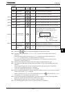
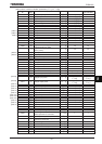
(Continued)
Commun
ication
No.
Item displayed
Key
operated
LED
display
Description
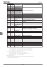
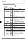
FE08 CPU1 version X
The version of the CPU1 is displayed.
FE73 CPU2 version
Y
The version of the CPU2 is displayed.
FE10
Past trip 1
E⇔ Past trip 1 (displayed alternately at 0.5-sec. intervals)
FE11
Past trip 2
J ⇔ Past trip 2 (displayed alternately at 0.5-sec. intervals)
FE12
Past trip 3
R⇔ Past trip 3 (displayed alternately at 0.5-sec. intervals)
FE13
Past trip 4
PGTT⇔ Past trip 4 (displayed alternately at 0.5-sec. intervals)
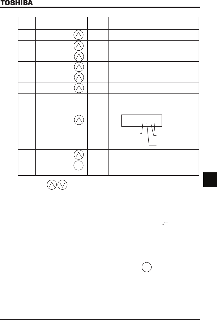
FE79
Part replacement
alarm information
O___
The ON/OFF status of each of the cooling fan, circuit
board capacitor, main circuit capacitor or part
replacement alarm of cumulative operation time is
displayed in bits.
ON:
OFF:_
FE14
Cumulative
operation time
V
The cumulative operation time is displayed.
(Indication of 0.1 represents 10 hours.)
Default display
mode
[Note 1]
The operation frequency is displayed (during operation).
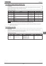
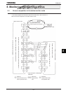
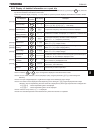
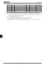
Note 1: Press the keys to change items displayed in the status monitor mode.
Note 2: Contents of status indications of *1, *2, *3, *4, *5, *6, *7, *8, and *9 can be selected from 44 kinds of
information.
Contents of status indications that are set up at H (standard monitor display selection) and
H~H (status monitor 1 to 8 display selection) are displayed.
Unit of current and voltage indications can be changed from % to A (ampere)/V (volt) and vice versa
respectively. Refer to Section 5.15.
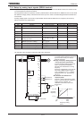
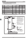
Note 3: Indicated input voltage is DC voltage just after input voltage is rectified multiplied by 1
2
.
Note 4: The number of bars displayed varies depending on the setting of H (logic output/pulse train output
selection.)
The bar representing the OUT1 terminal is displayed only when logic output function is assigned to it.
If H=: The bar representing OUT1 is displayed.
If H=: The bar representing OUT1 is not displayed.
Note 5: Past rip records are displayed in the following sequence: 1 (latest trip record) ⇔2⇔3⇔4 (oldest trip record).
If there is no trip record, PGTT is displayed.
Details on past trip record 1, 2, 3 or 4 can be displayed by pressing the
ENT
key when past trip 1, 2, 3 or
4 is displayed.
For more details, refer to Section 8.2.2.
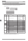
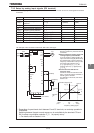
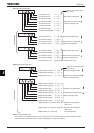
Note 6: The part replacement alarm is displayed based on the value calculated from the annual average ambient
temperature, operation time and load current specified using H.
Use this alarm as a guide only, since it is based on a rough estimation.
Note 7: The cumulative operation time increments only when the machine is in operation.
MODE
O___K
Cooling fan
Cumulative
operation time
Control circuit board
capacitor
Main circuit capacitor
[Note 6]
[Note 7]
[Note 5]
[Note 5]
[Note 5]
[Note 5]