


E6581301
F-81
6
6.39 Communication function
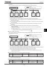
6.39.1 2-wire RS485/4-wire RS485
H
HH
H : Communication speed (2-wire RS485)
H
HH
H : Parity (2-wire RS485)
H
HH
H : Inverter number (common)
H
HH
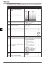
H :
Communications time-out time (common to 2-wire RS485 and 4-wire RS485)
H
HH
H :
Communications time-out action (common to 2-wire RS485 and 4-wire RS485)
H
HH
H : Send waiting time (2-wire RS485)
H
HH
H :
Master/slave setting for Inverter-to-inverter communications ( 2-wire RS485)
H
HH
H : Protocol selection (2-wire RS485)
H
HH
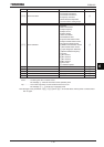
H : Communication1 time-out condition selection
H
HH
H : Frequency point selection
H
HH
H : Point 1 setting
H
HH
H : Point 1 frequency
H
HH
H : Point 2 setting
H
HH
H : Point 2 frequency
H
HH
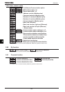
H : Communication speed (4-wire RS485)
H
HH
H : Send waiting time (4-wire RS485)
H
HH
H : Inverter-to-inverter communication setting (4-wire RS485)
H
HH
H : Parity (4-wire RS485)
H
HH
H : Protocol selection (4-wire RS485)
H
HH
H , H
HH
H : Block write data 1, 2
H
HH
H ~ H
HH
H : Block read data 1~5
H
HH
H : Free notes
For details, see Instruction Manual (E6581315) specified in Section 6.42.
•
••
• Function
These parameters allow you to connect the inverter to a higher-
level system (host) and to set up a network
for data communications between inverters. They make it possible for the inverter to be linked to a
computer and to carry out data communications with other inverters.
<Computer link function>
This function allows the inverter to carry out data communications with a higher-level system (host).
(1) Monitoring inverter status (such as the output frequency, current, and voltage)
(2) Sending RUN, STOP and other control commands to the inverter
(3) Reading, editing and writing inverter parameter settings
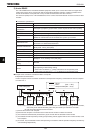
<Inverter-to-inverter communication function>
This function allows you to set up a network that makes it possible to carry out proportional operation of
multiple inverters (without using a computer).
Ŭ
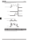
Timer function
......................................................
Designed to detect broken communications cables. If no
data is sent to the inverter within the specified time, this
function trips the inverter (“
GTT
” is displayed on the
display panel) or gives an alarm (“
V
” is displayed).
Ŭ
Broadcast function ......................................... Refers to the function of issuing a command (data writing)
to multiple inverters in one session.
Ŭ
Inverter-to-inverter communication function .. Refers to the function that enables the master inverter to
send the data selected with a parameter to all slave
inverters on the same network. This function allows you to
set up a network that makes it possible to carry out
synchronized operation or proportional operation (setting of
point frequencies) in an abbreviated manner.