


E6581301
C-5
3
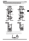
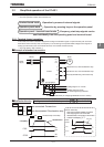
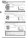
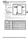
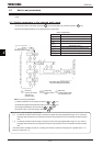
4) Setting the frequency using input voltage (0~10Vdc)
[Parameter setting]
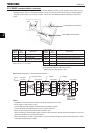
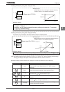
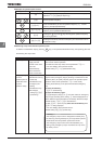
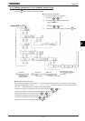
5) Setting the frequency using input voltage (0~±10Vdc)
The direction can be changed by switching between positive and negative signals.
[Parameter setting]
Set the “basic parameter frequency setting mode selection 1” parameter
HOQF
ҏ to
.
Note: Set reference frequency priority selection
H
to
(
HOQF
/
H
terminal switching, default setting).
Changing the settings of two speed command parameters at a time, refer to Section 6.6.
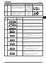
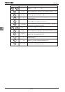
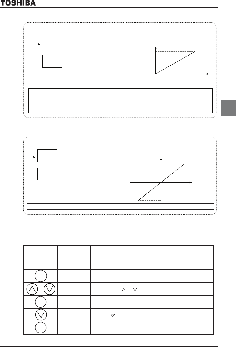
[Example of setting: To set the frequency by applying a current of 4(0)-20mAdc via the VI/II terminal.]
Key operated LED display Operation
Displays the operation frequency. (Perform during operation stopped.)
(When standard monitor display selection
H
=
[Output
frequency])
CWJ
Displays the first basic parameter “History function (
CWJ
).”
HOQF
Press either the or key to select “
HOQF
.”
Press the ENTER key to display the parameter setting (Default
setting:
).
Press the key to change the parameter to
.
⇔HOQF
Press the ENTER key to save the changed parameter.
HOQF
and the
parameter are displayed alternately.
MODE
Frequency
0
0Vdc
10Vdc
60Hz
Set the “extended parameter analog input VI/II voltage/current switching”
parameter
HOQF
to
.
In addition, set the “basic parameter frequency setting mode selection 1” parameter
H
to
(
default setting
)
.
+
-
RX
CCA
-10Vdc
+10Vdc
Forward run
Reverse run
60Hz
60Hz
+
-
ENT
ENT
V
I/
II
CCA
Ŭ
Voltage signal
Voltage signal (0~10V) for setting the operation frequency
Refer to Section 7.3 for details of adjustment.
:Voltage signal
0
-
10Vdc
Ŭ
Voltage signal
Voltage signal (0~±10V) for setting the operation frequency
Refer to Section 7.3 for details of adjustment.
:Voltage signal 0~±10Vdc