


E6581301
E-27
5
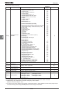
5.16 Meter setting and adjustment
HOUN
HOUNHOUN
HOUN
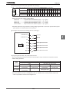
: FM terminal meter selection
HO
HOHO
HO
: FM terminal meter adjustment
H
HH
H
: Constant at the time of filtering
H
HH
H
: FM voltage/current output
switching
H
HH
H
: Inclination characteristic of FM
output
H
HH
H
: FM bias adjustment
H
HH
H
: FM output filter
COUN
COUNCOUN
COUN
: AM terminal meter
selection
CO
COCO
CO
: AM terminal meter
adjustment
H
HH
H
: Inclination characteristic
of AM output
H
HH
H
: AM bias adjustment
Note 1: The signal output from the FM and AM terminal is an analog voltage signal or an analog current signal.
(positive (+) side output. In the case of output the signed data, the signal is added offset. Offset level is able
to adjust by H and H. If monitoring the output data with positive and negative voltage, you need
to use "expansion I/O card2 option".
Note 2: To the FM terminal, connect either a full-scale 0~1mAdc ammeter or a full-scale 0~7.5Vdc (or 10Vdc)
voltmeter, if necessary. The FM terminal can also be used as a 0(4)~20mAdc output terminal.
To the AM terminal, connect either a full-scale 0~1mAdc ammeter or a full-scale 0~7.5Vdc (or 10Vdc)
voltmeter, if necessary.
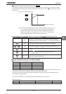
Connect meters as shown below.
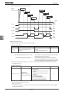
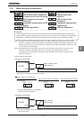
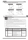
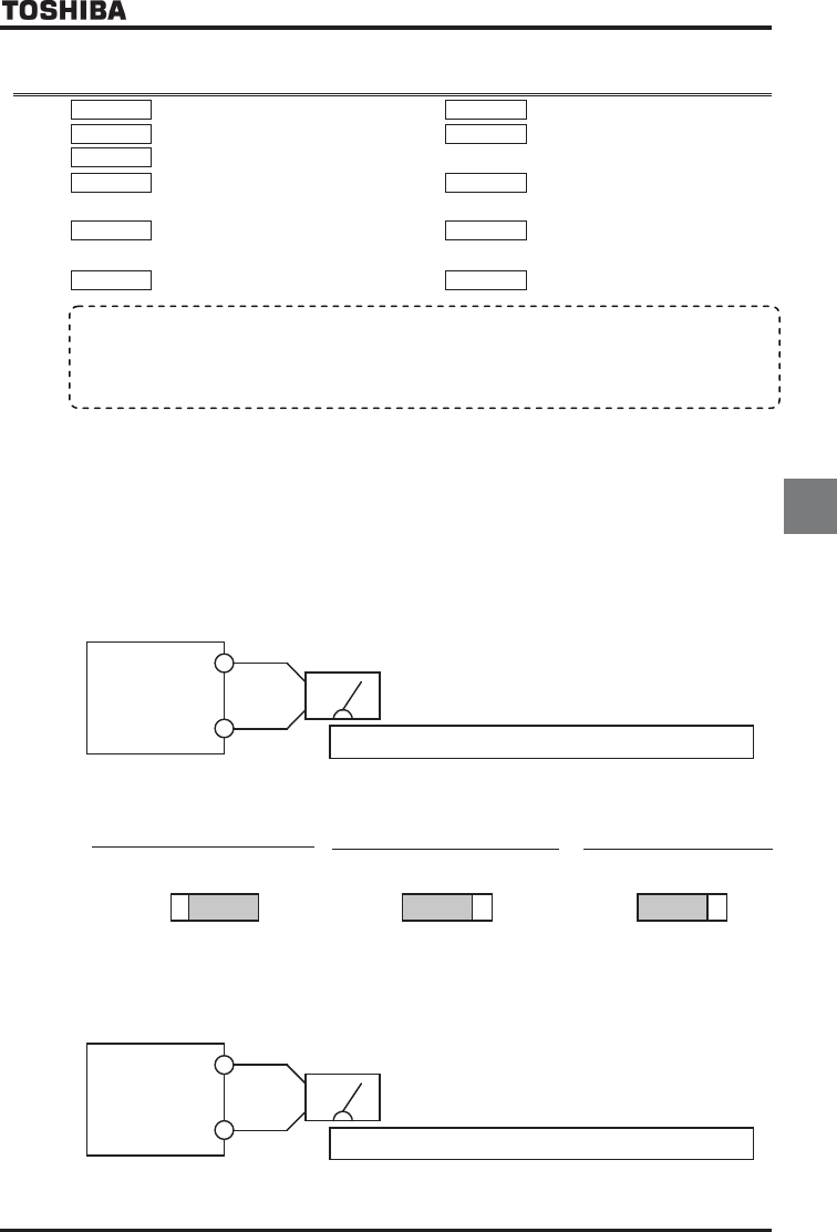
<Connection to terminal FM>
FM
CCA
VF-AS1
The reading of the frequency meter fluctuates during calibration.
Meter: Frequency meter
(default setting)
+
-
ŬA frequency meter QS60T is optionally available.
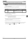
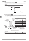
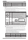
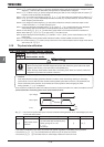
■
■■
■ Output modes of the FM terminal
0
-
10V
0-20mA
0
-
1mA
FM
When used with a 0~1mAdc ammeter
(Default setting)
SW2
When the optional frequency meter QS60T is
connected, this mode is selected.
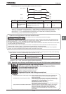
0
-
10V
0-20mA
0
-
1mA
F
M
When used with a DC0~10V voltmeter
SW2
H=
0
-
10V
0-20mA
0
-
1mA
FM
When used with a 0(4)~20mAdc
SW2
H=
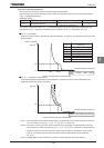
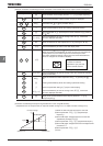
<Connection to terminal AM >
AM
CCA
VF-AS1
The reading of the ammeter fluctuates during calibration.
Meter: Ammeter
(default setting)
+
-
ŬIt is recommendable to use an ammeter with a current rating 1.5 or more times as high as the output current
rating of the inverter.
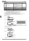
• Function
Inverter’s operation data is sent to the FM terminal (AM terminal) as analog voltage signals or analog current
signals. To display inverter’s operation data, connect a meter to this terminal. The “FM terminal-connected meter
adjustment HO” (AM terminal-connected meter adjustment CO) parameter is used to calibrate the meter
.