


E6581301
A-21
1
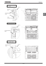
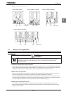
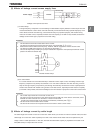
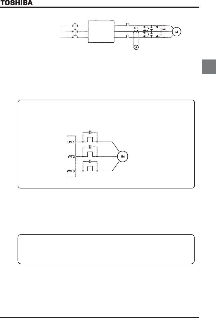
(2) Affects of leakage current across supply lines
Power supply
inverter
Thermal relay
Leakage current path across wires
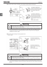
(1) Thermal relays
The high frequency component of current leaking into electrostatic capacity between inverter output wires will
increase the effective current values and make externally connected thermal relays operate improperly. If the
motor cables are more than 50m long, external thermal relay may operate improperly with models having
motors of low rated current, especially the 400V class low capacity (3.7/4.0kW or less) models, because the
leakage current will be high in proportion to the motor rating.
Remedies:
1. Use the electronic thermal overload built into the inverter.
The setting of the electronic thermal overload is done using parameter QNO or VJT.
2. Reduce the inverter's PWM carrier frequency. However, that will increase the motor's acoustic noise.
The setting of PWM carrier frequency is done with the parameter EH.
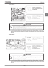
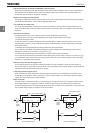
3. This can be improved by installing 0.1
ȝ
~0.5
ȝ
F-1000Vdc film capacitor to the input/output terminals of each
phase in the thermal overload relay.
Thermal overload relays
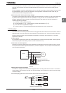
(2) CT and ammeter
If a CT and ammeter are connected externally to measure inverter output current, the leakage current's high
frequency component may destroy the ammeter or CT. If the motor cables are more than 50m long, it will be
easy for the high frequency component to pass through the externally connected CT and be superimposed on
and burn the ammeter with models having motors of low rated current, especially the 400V class low capacity
(3.7/4.0kW or less) models, because the leakage current will increase in proportion to the motor's rated current.
Remedies:
1. Use a meter output terminal in the inverter control circuit.
The output current can be output on the meter output terminal (AM, FM). If the meter is connected, use an
ammeter of 1mAdc full scale or a voltmeter of 7.5Vdc-1mA full scale.
Inverter output terminal (FM) can be changed to 0-20mAdc (4-20mAdc) with H.
2. Use the monitor functions built into the inverter.
Use the monitor functions on the panel built into the inverter to check current values.
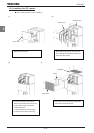
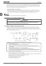
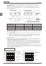
(3) Affects of leakage current by cable length
The cable length from inverter to motor is no more than 100m. When you connect an inverter to several motors, the total
cable length is no more than 100m. Especially for 3.7kW or less inverter will be made overcurrent protection by the
charge current in cable capacitance. In this case, decrease the electrostatic capacity by separates of the cable or set
filter (MSF series) on output side of the inverter.