


E6581301
B-16
2
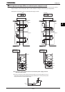
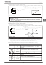
2.3.3 RS485 communication connector
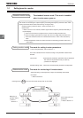
The VF-AS1 is equipped with two connectors: a two-wire RS485 connector (on the operation panel) and a four-wire
RS485 connector. The two wire RS485 connector is used to connect an external option (such as remote keypad or
computer) to the inverter. To connect to a network, use the four-wire RS485 connector, following the instructions
below.
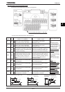
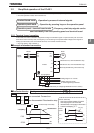
2-wire RS485 4-wire RS485
Signal
name
Pin
number
Description
Signal
name
Pin
number
Description
DA 4 Same phase data RXA 4 Same phase reception data (positive line)
DB 5 Anti-phase data RXB 5 Anti-phase reception data (positive line)
SG 8 Ground line of signal data TXA 3 Same phase transmitting data (positive line)
This table shows signal line of inverter side. TXB 6 Anti-phase transmitting data (positive line)
* Never use pin-1, 2, 3, 6 and 7. SG 2, 8 Ground line of signal data
This table shows signal line of inverter side.
(Example: RXA signal is received by inverter.)
* Never use pin-1 (P24) and pin-7 (P11).
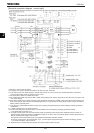
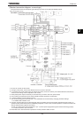
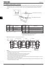
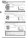
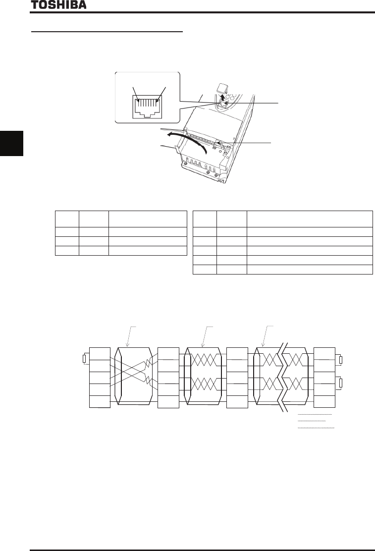
■ CRQQHFWLRQ diagram for 4-wire RS485 communication
Terminating
resistance
100
Ω
-1/4W
AS1 (slave)
Upper computer
or VF-
AS1
(master)
RXA
RXB
TXA
TXB
SG
RXA
RXB
TXA
TXB
SG
RXA
RXB
TXA
TXB
SG
RXA
RXB
TXA
TXB
SG
cross each other
straight
straight
AS1 (slave)
AS1 (slave)
■ Note
* Separate the communication line and the main circuit wiring by 20cm or more.
* Never use pin-1 (P24) and pin-7 (P11).
* Connect RXA and RXB, between TXA and TXB using twisted pair cable.
* Connect terminating resistances at both ends of a transmission line.
* When using 2-wire type, short RXB to TXB and RXA to TXA.
When connecting a communications device via the two-wire connector, carefully read the precautions for use in the
operating manual for the communications device.
* When connecting the VF-AS1 to other inverters, you do not need to connect the master receive lines (pins 4 and 5)
or the slave send lines (pins 3 and 6).
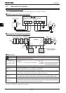
2-wire RS485 communication
4-wire RS485 communication
Pin-1 Pin-8