


E6581301
G-5
7
■ Sink logic/source logic
Switching between sink logic and source logic (input/output terminal logic) is possible.
For details, refer to the Section 2.3.2.
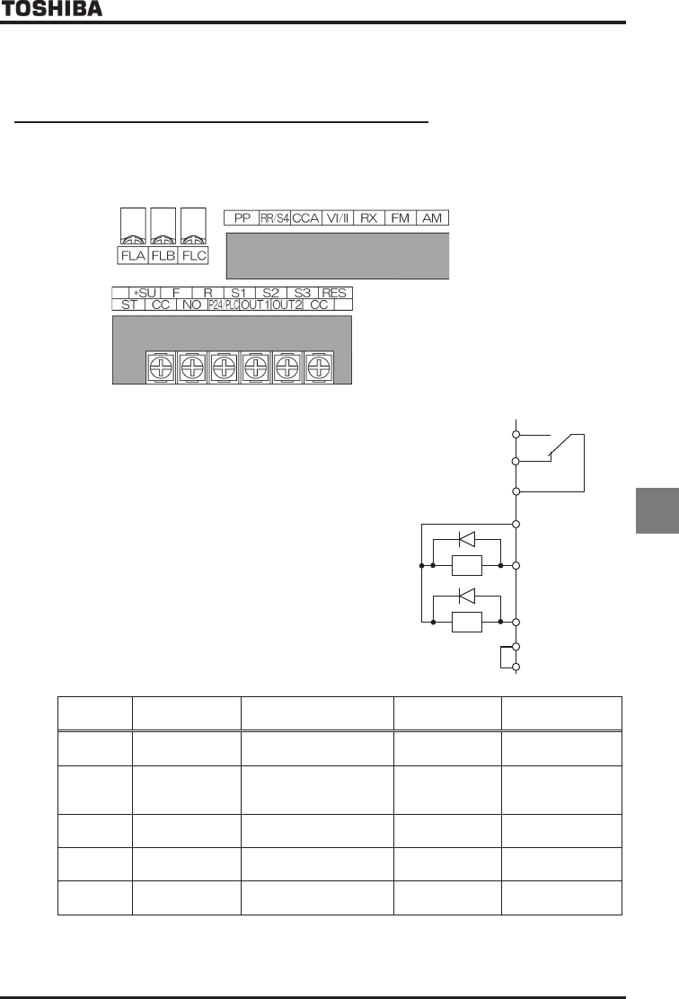
7.2.2 Functions of output terminals (incase of sink logic)
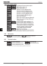
Use the above parameters to send various signals from the inverter to external equipment.
By setting parameters for the OUT1, OUT2 and FL (FLA, FLB and FLC) terminals on the terminal board, you can use
0~255 functions and functions obtained by combining them.
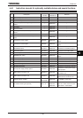
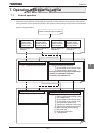
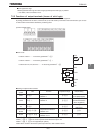
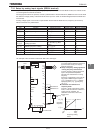
[Control terminal board]
■ How to use
Function of OUT1··········To be set by parameter H
Function of OUT2··········To be set by parameter H
Functions of FLA, FLB, and FLC··········To be set by parameter H
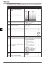
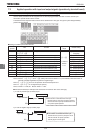
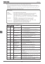
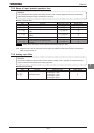
■ Setting of output terminal function
Terminal
symbol
Title Function Adjustment range Default setting
OUT1 H
Output terminal function
selection 1
~
(Low-speed signal)
OUT2 H
Output terminal function
selection 2 ~
(Acceleration/decele
ration completion)
FL H
Output terminal selection 3
~
(Failure FL)
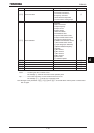
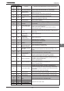
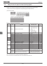
OUT3~OUT6
R1~R2
H
~
H
Output terminal function
selection 4~9
~
R3, R4 H, H
Output terminal function
selection 10~11
~
Note1: H~H is for use of expansion terminal board 1 option unit.
Note2: H~H is for use of expansion terminal board 2 option unit.
Note3: H, H is not supported (for options).
Note4: When use OUT1 terminal for pulse output function, refer to Section 6.35.1.
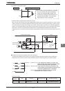
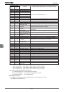
FLA
FLB
P24
OUT1
FLC
OUT2
Ry
Ry
NO
CC