E6581301
M-6
13
(Continued overleaf)
(Continued)
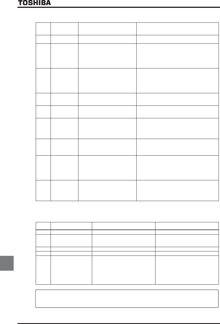
KPKV
Parameters in
the process of
initialization
•Parameters are being initialized to
default values.
•Normal if the message disappears after a while
(several seconds to several tens of seconds).
CVP
In auto-tuning 1
•Auto-tuning 1 in process. •Normal if it the message disappears after a few
seconds.
NUVR
Auto-stop
because of
continuous
operation at the
lower-limit
frequency
•The automatic stop function of
H is being performed.
•This function is deactivated when the command
frequency becomes 0.2Hz or more higher than the
lower-limit frequency (LL) or when a command for
stopping operation is entered.
UVQR
Momentary
power failure
slowdown stop
prohibition
function
activated.
•The deceleration stop function of
WXE (regenerative power
ride-through control) is activated.
•To restart operation, reset the inverter or input an
operation signal again.
JGCF/
GPF
Display of
first/last data
items
•First and last data in the CWJ
group.
•To exit from the group, press the MODE key.
VWP
During learning
•Learning for brake sequence
operation or light-load high-speed
operation is currently in progress.
•To cancel learning, suspend it and set learning
parameters H to .
VWP
Brake sequence
learning error
•Braking operation is not performed
normally.
•The load is too heavy.
•There are some operation errors.
•Brake signal output (, ) is not assigned to
the control output terminal.
•The brake function mode selection parameter
(H) is not set.
•Learning is performed while the load is lifted
VWP
Light-load
high-speed
learning
operation error
•There are some errors in the
operation for learning for light-load
high-speed operation.
•Check whether the learning operation for light-
load
high-speed operation is performed correctly.
Refer to 6.16.
VWP
Light-load
high-speed
learning
overload error
•Learning operation for light-load
high-speed operation is performed
while the load is lifted.
•Motor constants (XN, XNX,
H to H) are not
entered correctly.
•Check the load.
•Check the motor constant setting.
WPFZ
Key operation
permitted
temporarily
•This message appears if the
ENTER key is pressed and held
down for 5 seconds or more when
key operation is prohibited by
H.
•When this message is displayed, all the keys are
operational. To prohibit key operation again, turn
off the inverter and then turn it back on.
Note: In the case of DC injection breaking ON/OFF function is selected for an input terminal; if “FD” disappears as a
result of open-circuit between the terminal and CC, it is normal.
[Pre-alarm display]
Error
code
Description Possible causes Remedies
E Overcurrent pre-alarm Same as QE (Overcurrent) Same as QE (Overcurrent)
R Overvoltage pre-alarm
Achieving PBR operation
level
Same as QR (Overvoltage)
R blink while PBR is operating is not
an error.
Same as QR (Overvoltage)
R blink while PBR is operating is not
an error.
N Overload pre-alarm Same as QN and QN (Overload) Same as QN and QN (Overload)
J Overheat pre-alarm Same as QJ (Overheat) Same as QJ (Overheat)
V Communication error •Various transmission errors occur
when computer is linked up with
inverter system.
•Various transmission errors occur in
inverter to inverter communication
(slave side). Time-out or trip in master
side.
•For measures to correct various kinds
of data transmission errors, refer to
the instruction manual for the
communications device used
specified in Section 6.42.
•Check the master inverter.
If two or more problems arise simultaneously, one of the following alarms appears and blinks.
ER, RN, NJ, ERN, ……, ERNJ
The blinking alarms E, R, N, J, Vare displayed in this order from left to right.


