


E6581301
F-15
6
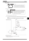
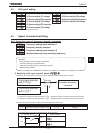
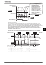
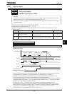
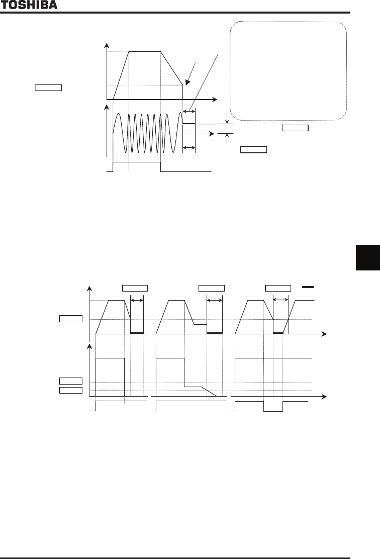
ON
OFF
Time [s]
DC braking start frequency
H
DC braking current
H
DC braking time
H
Output frequency [Hz]
DC braking
Operation signal (F-
CC)
(SW1 set to sink logic)
Output current [A]
0
0
Set frequency
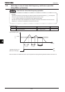
Note:
During DC braking, the DC braking
current may be adjusted
automatically to prevent the
overload protection function from
being activated and causing the
inverter to trip.
The DC braking current may be
adjusted automatically to prevent
tripping.
When the inverter is used with a
standard motor, setting the
percentage of DC braking (
H
)
above 60% may activate the thermal
protection function to prevent the
motor from being overloaded,
depending on the setting of
H
(DC braking time).
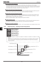
LED display
FD
displayed
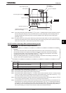
<DC braking start conditions>
The forward/reverse DC braking priority control function H recognizes certain conditions such as stop
commands from the inverter, and is activated when the output frequency goes down below the DC braking start
frequency set with H. In this case, the conditions under which DC braking starts include not only the issue of a
start or stop command from the operation panel or an external input device, but also a fall in the reference
frequency below the value set with H (stop frequency setting) or a fall in the output frequency below the
operation stop frequency setting H.
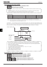
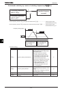
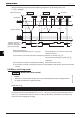
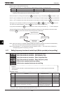
[DC braking under normal conditions] (Forward/reverse run DC braking priority control H= [Disabled])
ON
OFF
Time [s]
: DC braking
H
H
Output frequency [Hz]
Operation signal (F-CC)
(SW1 set to sink logic)
Reference frequency
0
0
Set frequency
~
~
G
~
~
G
G
G
G
~
~
G
~
~
G
~
~
~
~
H
H
H
H
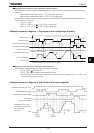
(1) (2) (3) (2)
(1) If H and H > reference frequency : DC braking
(2) If H > reference frequency > H : Operation at the command frequency
If H and H > reference frequency : DC braking
(3) If an operation command is entered during DC braking : DC braking is discontinued to restart the operation.