


E6581301
M-3
13
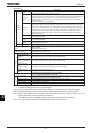
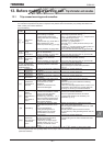
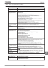
(Continued)
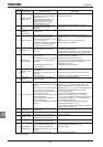
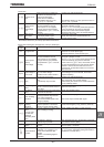
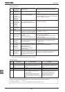
Error
code
Description Possible causes Remedies
G Emergency stop
•Inverter is stopped by panel
operation during automatic or
remote operation.
•A stop command (input terminal
function: or ) is issued by
an external control device.
•Reset the inverter.
GGR
EEPROM error
•A data writing error occurs.
•Turn off the inverter, then turn it again. If it does
not recover from the error, Contact your Toshiba
distributor.
GGR
Initial read error
•Some internal data is corrupted.
•Power was turned off while V[R
was being set.
•Contact your Toshiba distributor.
•Set V[R again. If the inverter does not recover
from the error, Contact your Toshiba distributor.
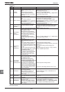
GGR
I
nitial read error
•Some internal data is corrupted.
•Contact your Toshiba distributor.
GH
GH
Ground fault
•A current leaked from an output
cable or the motor to ground.
•Check the cable and the motor for ground faults.
*
GRJ
Output phase
failure
•A p
hase failure occurred in the
output line of the main circuit.
•
The
motor
is not
connected.
•Check the main circuit output line, motor, etc. for
phase failure.
•
Select output phase failure detection parameter
H
.
•
Make sure that a motor is connected.
*
GRJ
Input phase
failure
•A phase failure occurred in the
input line of the main circuit.
•Check the main circuit input line for phase failure.
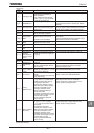
GTT
Main unit RAM
fault
•The control RAM is defective.
•Contact your Toshiba distributor.
GTT
Main unit RO
M
fault
•The control ROM is defective.
•Contact your Toshiba distributor.
GTT
CPU fault
•The control CPU is defective.
•Contact your Toshiba distributor.
GTT
Interruption of
operation
command from
external control
device
•
A normal communication was not
possible for the time or longer set
by H.
•Check the remote control device, cables, etc.
GTT
Gate array fault
•Main gate array is defective.
•Contact your Toshiba distributor.
GTT
Output current
detector error
•The main output current detector
is defective.
•Contact your Toshiba distributor.
GTT
Optional unit
fault
•An optional device has failed.
(such as a communication device
[add
-
on option])
•Check the connection of optional board(s).
•Refer to instructions of options concerned
specified in Sec
tion 6.42
.
GTT
Extended panel
option. cable is
broken
•
10 seconds
disconnection
is
detected by the setting H=0
(disconnection detection)
•
Confirm the connection
between extended panel
option (RKP002Z,RKP004Z) and inverter.
GVP
Tuning error
•
It was
unable to auto tuning
normally.
•The internal system error occurred
during auto tuning
.
•
Perform auto
-
tuning
1
again and if the error
persists, contact your Toshiba distributor.
GVP
Tuning
detection error
•
Some of
H
,
H
,
H and H were not to
be detected during auto tuning.
•The capacity of the motor
connected is 2 notches or more
smaller than the inverter capacity.
•The motor connected is not a
three-phase inductive motor.
•Tuning is performed while no
motor is connected.
•The cables connecting the inverter
to the motor are too long; they are
more than 30m in length.
•Tuning is performed while the
motor is running.
•
Make sure that a motor is connected.
•Make sure that the motor is at standstill.
•Perform auto-tuning 1 again and if the error
persists, perform tuning manually.
GVP
Motor constant
value error
•
Some detection values
of
H,H,H and
H were beyond the limits of
normal value.
•The capacity of the motor
connected is 2 notches or more
smaller than the inverter capacity.
•The motor connected is not a
three-phase inductive motor.
•The cables connecting the inverter
to the motor are too long; they are
more than 30m in length.
•Tuning is performed while the
motor is running.
•
Make sure that the motor is at standstill.
•Perform auto-tuning 1 again and if the error
persists, perform tuning manually.
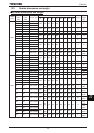
*Presence or absence of parameter trip can be selected.
(Continued overleaf)