


E6581301
I-3
9
(2) Use shielded power cables and control signal cables for the input and output lines of the inverter. Route the
cables and wires so as to minimize their lengths. Keep a distance between the power cable and the control cable
and between the input and output wires of the power cable. Do not route them in parallel or bind them together,
instead cross at right angle.
(3) Install the inverter in an enclosed steel cabinet, it is more effective in limiting the radiation. Using wires as thick
and short as possible, earth the control panel securely with a distance kept between the earth cable and the
power cable.
(4) To limit the radiation noise from cables, earth each shielded cable to the EMC plate. It is effective to earth
shielded cables in the vicinity of the inverter and filter (within a radius of 10cm from each of them). Inserting a
ferrite core in a shielded cable is even more effective in limiting the radiation noise.
(5) To further limit the radiation noise, insert a zero-phase reactor in the inverter output line and insert ferrite cores in
the earth cables of the EMC and cabinet.
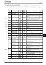
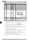
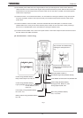
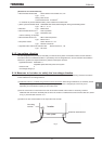
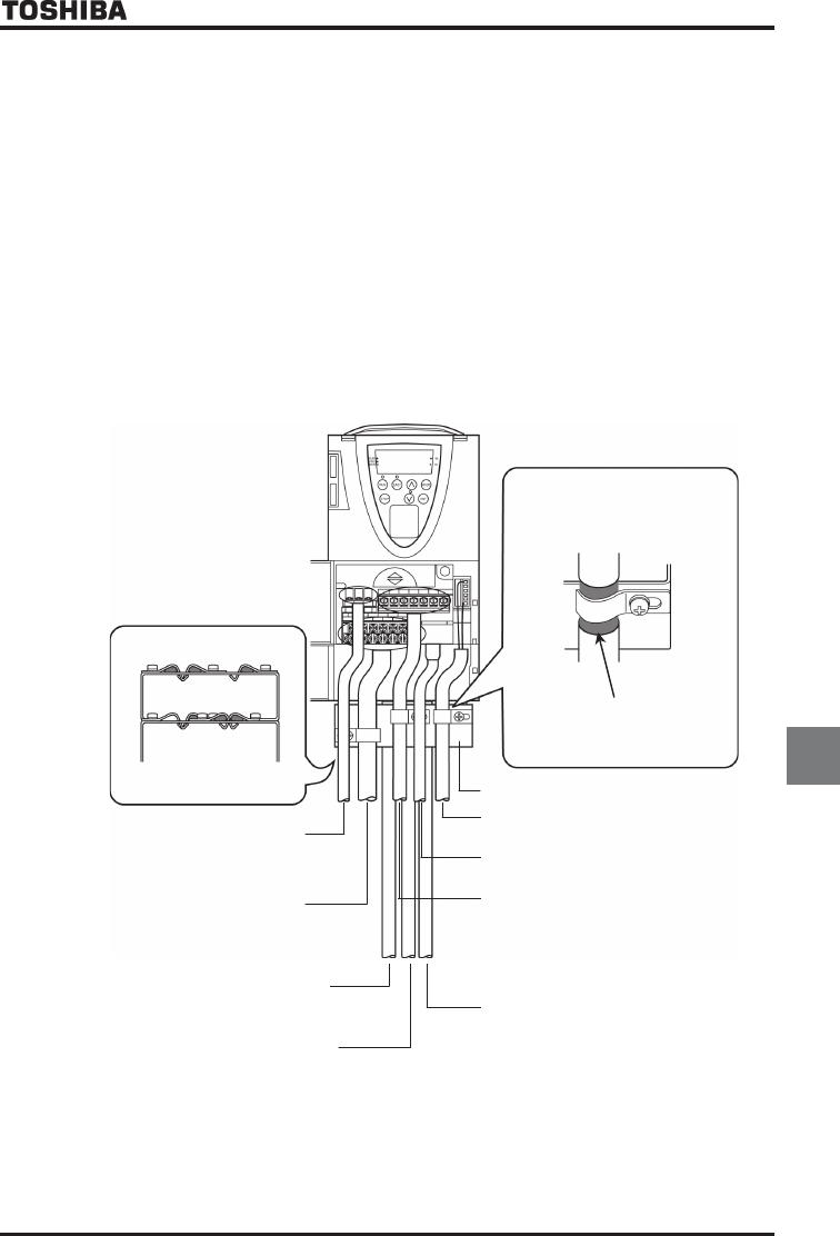
[Ex. Countermeasure - inverter wiring]
Peel off the outer sheath of the
cable and fix the shielded part with
a metal saddle.
Strip and earth the shielded cable,
following the example shown in
Fig.
Control wiring (Shielded cabless)
Relay contact output FLA, FLB, FLC
Control wiring (Shielded cabless)
Analog input VI/II, RR/S4, PP, CCA
Analog output FM, AM, CCA
PG feedback signal line (Shielded cabless)
Power supply wiring (Shielded cabless)
R/L1, S/L2, T/L3
Motor wiring (Shielded cabless)
U/T1, V/T2, W/T3
Braking resistor wiring (Shielded cabless)
PA/+, PB
EMC
plate
(Refer to Table 2.)
4-
wire RS485 communication line (Shielded cabless)
Control wiring (Shielded cabless)
Logic input/output +SU, F, R, S1
᳸
S3, RES,
ST, NO, P24/PLC, OUT1,
OUT2, CC
Fig. 1