


E6581301
11
K-12
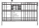
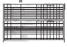
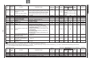
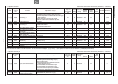
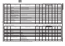
[12] Tripless intensification setup [2/2] Sensorless vector/vector with sensor (Ɣ:Effective, -:Ineffective)
Title
Communi
cation
No.
Function Adjustment range
Minimum
setting unit
(Panel/Communi
cation)
Default
setting
Write during
running
Vector control
PM
control
V/f Reference
Speed
control
Torque
control
H
0307
Base frequency voltage
selection
(correction of supply voltage)
0:
Without voltage compensation (limitless output voltage)
1:
With voltage compensation (limitless output voltage)
2:
Without voltage compensation (limited output voltage)
3:
With voltage compensation (limited output voltage)
1/1 0 Disabled
Parameter is changeable, but fixed to
"with voltage compensation" internally.
When
H
is set to 0 or 1, fixed at
1 internally.
When
H
is set to 2 or 3, fixed at
3 internally
.
Ɣ 6. 14. 3
RDT
0308
Dynamic braking resistance
0.5~1000
0.1
/0.1
*
1
Disabled
Ɣ
/
Ɣ
Ɣ
/
Ɣ
Ɣ
Ɣ
5. 19
RDER
0309
Dynamic braking resistor capacity
0.01~600.0kW
0.01/
0.01
*
1
Disabled
Ɣ
/
Ɣ
Ɣ
/
Ɣ
Ɣ
Ɣ
5. 19
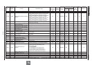
H
0310
Non
-
stop control time/deceleration
time during power failure
0.1~320.0 sec. 0.1/0.1 2.0
Enabled
*3/
Disabled
Ɣ/Ɣ -/- Ɣ Ɣ 5. 18. 2
H
0311
Reverse
-
run prohibition
selection
0:Permit all
,
1:Prohibit reverse ru
n
2:Prohibit forward run
1/1 0 Disabled Ɣ/Ɣ Ɣ/Ɣ Ɣ Ɣ 6. 14. 4
H
0312
Random mode
0:Disabled, 1:
Enabled
1/1
0
Disabled
Ɣ
/
Ɣ
Ɣ
/
Ɣ
Ɣ
Ɣ
5. 17
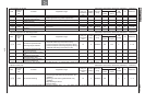
H
0313
Output voltage waveform
selection *4
0:
PWM carrier frequency control 1
1:
PWM carrier frequency control 2
1/1 0 Disabled Ɣ/Ɣ Ɣ/Ɣ Ɣ Ɣ 6. 14. 5
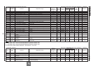
H
0316
Carrier frequency control mode
selection
0:Not decrease carrier frequency automatically
1:Decrease carrier frequency automatically
2:Not decrease carrier frequency automatically,
400V class supported
3:Decrease carrier frequency automatically, 400V
class supported
4:Not decrease carrier frequency automatically,
with sinusoidal filter
5:Decrease carrier frequency automatically, with
sinusoidal filter
1/1 *1 Disabled Ɣ/Ɣ Ɣ/Ɣ Ɣ Ɣ 5. 17
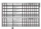
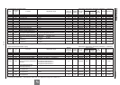
H
0317
Synchronized dece
leration time
(time elapsed between start of
deceleration to stop)
0.1~6000 sec. 0.1/0.1 *2 2.0 Enabled Ɣ/Ɣ -/- Ɣ Ɣ 5. 18. 2
H
0318
Synchronized
acceleration
time
(time elapsed between start of
acceleration to achievement of
specified speed)
0.1~6000 sec. 0.1/0.1 *2 2.0 Enabled Ɣ/Ɣ -/- Ɣ Ɣ 5. 18. 2
H
0319
Regenerative over
-
excitation
upper limit
100~160% 1/1 140 Disabled Ɣ/Ɣ Ɣ/Ɣ - Ɣ 6. 14. 2
This parameter moves to a fundamental parameter. *1: Default values vary depending on the capacity. See the table of K-48.
*2: Changing the parameter V[R enables to set to 0.01 sec. (adjustment range: 0.01~600.0 sec.).
*3: Although the setting can be written into memory if WXE is set to (power ride-through control), it cannot be written if WXE is set to (deceleration stop during a power failure).
*4:H is available for VFAS1-2550P, VFAS1-4900PC and above.
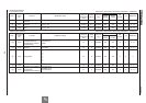
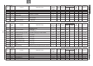
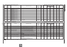
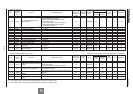
13] Drooping control Sensorless vector/vector with sensor (Ɣ:Effective, -:Ineffective)
Title
Communi
cation
No.
Function Adjustment range
Minimum
setting unit
(Panel/Communi
cation)
Default
setting
Write during
running
Vector control
PM
control
V/f Reference
Speed
control
Torque
control
H
0320
Drooping gain
0
.0
~100
.0
% (Enabled if
RV
=3,
4,
7 or 8)
0.1
/0.1
0.0
Enabled
*1
Ɣ
/
Ɣ
-
-
-
6. 15
H
0321
Speed at drooping gain 0%
0.0~320.0Hz (Enabled if
RV
=3,
4,
7 or 8)
0.1/0.01
0.0
Enabled
Ɣ
/
Ɣ
-
-
-
6. 15
H
0322
Speed at drooping gain
H
0.0~320.0Hz (Enabled if
RV
=3,
4,
7 or 8)
0.1/0.01
0.0
Enabled
Ɣ
/
Ɣ
-
-
-
6. 15
H
0323
Drooping insen
sitive torque
0~100% (Enabled if
RV
=3,
4,
7 or 8)
1
/1
10
Enabled
Ɣ
/
Ɣ
-
-
-
6. 15
*1: Drooping gain can be changed within a range of 0.1 to 100.0% during operation. When changing the setting to 0.0 (no drooping) or 0.0, stop operation.