


E6581301
F-6
6
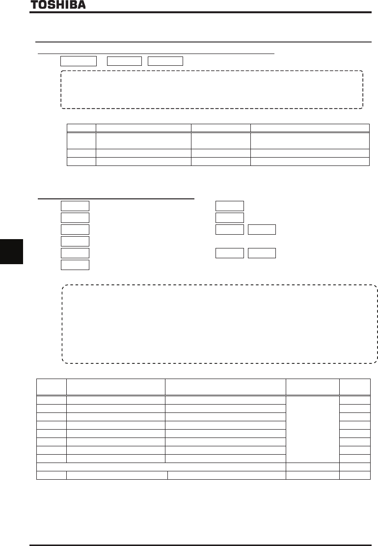
6.3 Terminal function selection
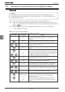
6.3.1 Keeping an input terminal function always active (ON)
H
HH
H , H
HH
H , H
HH
H
: Always ON function selection 1
~
3
• Function
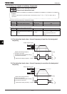
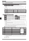
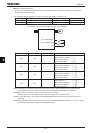
This parameter specifies an input terminal function that is always kept active (ON). (Only one function
selectable)
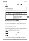
[Parameter setting]
Title Function Adjustment range Default setting
H
Always ON function selection 1 ~
Inverter with a model number ending with
-WN, HN: -WP:
H
Always ON function selection 2 ~
H
Always ON function selection 3 ~
* The selected function is always kept active regardless of the type of logic (positive or negative) in the table of
function settings in 7.2.1.
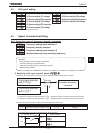
6.3.2 Modifying input terminal functions
H
HH
H
: Input terminal function selection 1 (F)
H
HH
H
: Input terminal function selection 2 (R)
H
HH
H
: Input terminal function selection 3 (ST)
H
HH
H
: Input terminal function selection 4 (RES)
H
HH
H
: Input terminal function selection 5 (S1)
H
HH
H
: Input terminal function selection 6 (S2)
H
HH
H
: Input terminal function selection 7 (S3)
H
HH
H
: Input terminal function selection 8 (RR/S4)
H
HH
H
~
H
HH
H
:
Input terminal function selection 9~16
H
HH
H
~
H
HH
H
:
Input terminal function selection 17~20
For details, refer to Section 7.2.1.
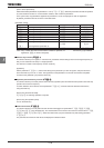
■
■■
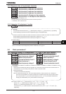
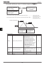
■ Setting of contact input terminal function
Terminal
symbol
Title Function Adjustment range
Default
setting
– H [Note 3], H, H
Always ON function selection 1~3
~
(
Refer to
Section 11.)
F H Input terminal function selection 1 (F) (F)
R H Input terminal function selection 2 (R) (R)
ST H [Note 4], H Input terminal function selection 3 (ST) (ST)
RES H Input terminal function selection 4 (RES) (RES)
S1 H Input terminal function selection 5 (S1) (S1)
S2 H Input terminal function selection 6 (S2) (S2)
S3 H Input terminal function selection 7 (S3) (S3)
The terminal below is operative only when SW3 is in the S4 position. – –
RR/S4 H Input terminal function selection 7 (S4) ~ [Note 2] (S4)
Note 1: The function that has been selected using H, Hand H (always ON function selection 1~3
parameter) are always activated.
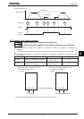
Note 2: When using the RR/R4 terminal as a contact input terminal (sink logic), always move the SW3 slide switch to
the S4 position.
Note 3: VFAS1-****-WN, HN
Note 4: VFAS1-****-WP
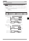
• Function
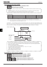
Use the above parameters to send signals from an external programmable controller to various control input
terminals to operate and/or set the inverter.
The desired contact input terminal functions can be selected from 120 types (-). This gives system design
flexibility.
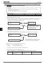
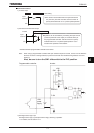
Using the SW3 switch, the function of the RR/S4 terminal can be selected between analog input and contact input.
By default, the RR/S4 terminal is set as an analog input terminal (voltage input terminal). To use it as a contact input
terminal, you need to
m
ove
the SW3 switch to the
S4
position.