


E6581301
F-1
6
6. Extended parameters
Extended parameters are provided for sophisticated operation, fine adjustment and other special purposes.
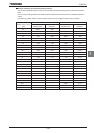
Refer to Section 11, Table of parameters.
6.1 Input/output parameters
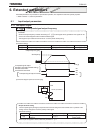
6.1.1 Low-speed signal
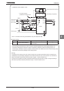
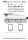
H
HH
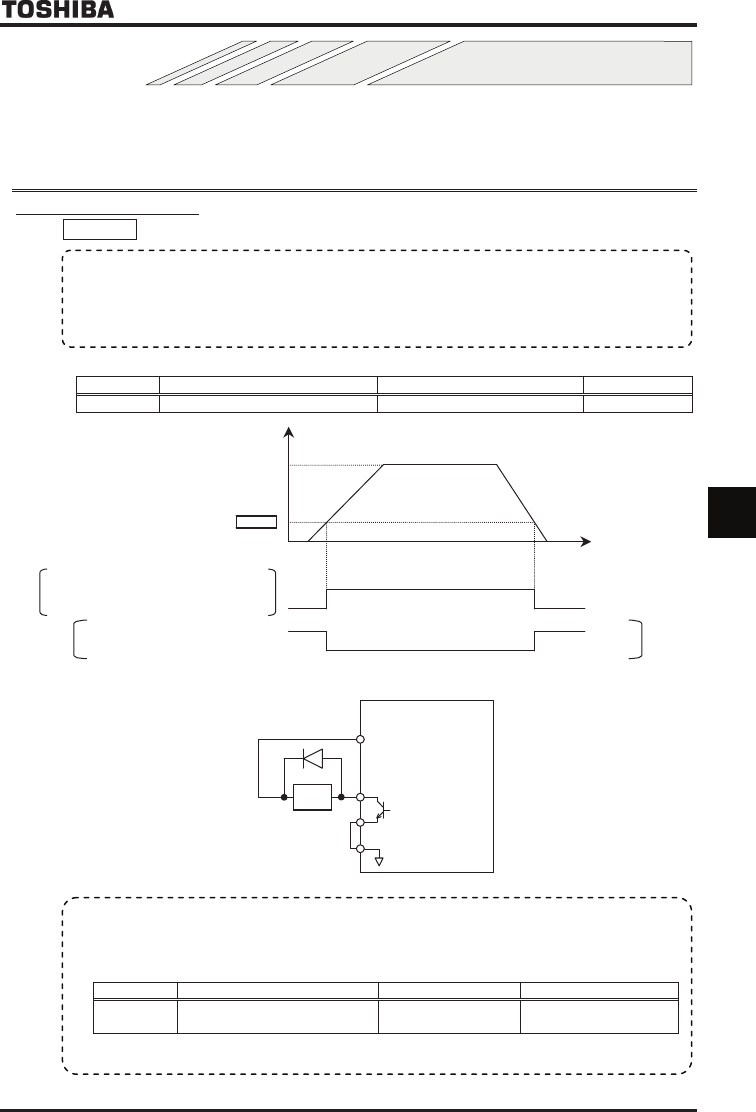
H : Low-speed signal output frequency
[Parameter setting]
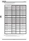
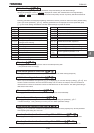
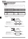
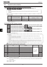
Title Function Adjustment range Default setting
H Low-speed signal output frequency ~WN Hz
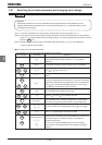
Output frequency [Hz]
Time [s]
H
Low-speed signal output
P24-OUT1 terminals (Default setting)
P24-OUT2 terminals
FLA-FLB-FLC terminals
ON
OFF
Low-speed signal output: Inverted
ON
OFF
0
Set frequency
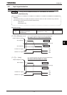
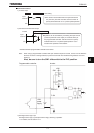
[Connection diagram (SW1 set to sink logic)]
P24
OUT1 (or OUT2)
NO
CC
Ry
• Function
When the output frequency exceeds the setting of H an ON signal will be generated. This signal can be
used as an electromagnetic brake excitation/release signal.
★Through the open collector terminal OUT1 or OUT2 (24Vdc-50mA [max.]).
• Output terminal setting
The low-speed signal (ON signal) output function has been assigned to the terminal OUT1 by default. This
setting must be changed to invert the polarity of the signal.
[Parameter setting]
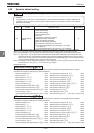
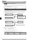
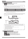
Title Function Adjustment range Example of setting
H
Output terminal function selection
1(OUT1)
~
(ON signal) or
(OFF signal)
Note: To put out signals to OUT2, select the parameter H.