


E6581301
H-8
8
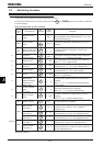
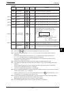
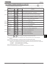
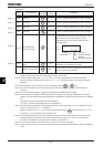
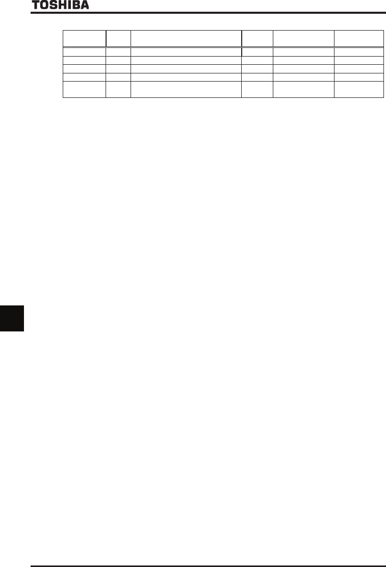
(Continued)
Communication
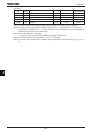
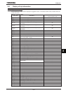
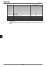
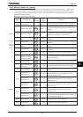
No.
Default
setting
Item displayed Marking Unit (Panel)
Unit
(Communication)
FE56
RP 0.1% 0.01%
FD85
COUNT1
1 1
FD86
COUNT2
1 1
FD52
PID result frequency
0.1Hz 0.01Hz
FE84
Synchronous speed frequency
command
0.1Hz 0.01Hz
Note 1: If any value other than the values in the above table is specified, the number “” is displayed.
Note 2: If a negative value of signed signal is specified, the negative sign “-” is displayed. When the negative sign “-”
is displayed, do not display "S", "E", "L". When read through by communications device, the negative sign is
affixed only FE18~FE20, FE37 and FE38 values..
Note 3: Data set with FA65-FA79 is displayed.
For details, refer to Instruction Manual (E6581315) specified in Section 6.42.
Note 4: Unit of display is able to change depends on H~ H setting.
Note 5: If monitor this item, operate a motor in automatic torque boost mode or vector control mod (RV=,,, or
)