


E6581301
M-2
13
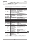
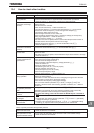
(Continued)
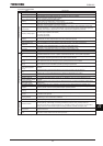
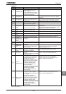
Error
code
Description Possible causes Remedies
QN
Inverter
overload
•R
apid
acceleration is
operated
.
•The DC braking amount is too
large.
•The V/f setting is improper.
•A restart signal is input to the
rotating motor after a momentary
stop, etc.
•The load is too large.
•Increase the acceleration time
CEE
.
•Reduce the DC braking amount H and the
DC braking time H.
•Check the V/f parameter setting.
•Use WX (Auto-restart) and WXE (Regenerative
power ride-though control).
•Use an inverter with a larger rating.
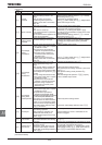
QN
Motor overload
•
The V/f parameter is improperly
set.
•The motor is locked up.
•Low-speed operation is performed
continuously.
•An excessive load is applied to the
motor during operation.
•Check the V/f parameter setting.
•Check the load (operated machine).
•Check the QNO setting and adjust H
according to the sustainable overload in the motor
low-speed range.
•Reduce the DC braking amount H and the
DC braking time H.
QNT
Dynamic
braking resistor
overload
•
Rapid
deceleration is
operated
.
•Dynamic braking is too large.
•Increase the deceleration time
FGE
.
•Increase the capacity of dynamic braking resistor
(wattage) and adjust PBR capacity parameter
RDER
.
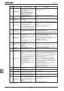
QR
Overvoltage
during
acceleration
•
The input voltage fluctuates abnormally.
(1)The power supply has a capacity
of 500kVA or more.
(2)A power factor improvement
capacitor is opened and closed.
(3)A system using a thyrister is
connected to the same power
distribution line.
•A restart signal is input to the
rotating motor after a momentary
stop, etc.
•Insert a suitable input reactor.
•Use WX (Auto-restart) and WXE (Regenerative
power ride-though control).
QR
Overvoltage
during
deceleration
•
The decel
eration time
FGE
is too
short (regenerative energy is too
large).
•The dynamic braking resistor has
a considerably large resistance.
•
RD
(Dynamic braking resistor) is OFF.
Overvoltage limit operation H
is OFF.
•
The input voltage fluctuates abnormally.
(1)The power supply has a capacity
of 500kVA or more.
(2)A power factor improvement
capacitor is opened and closed.
(3)A system using a thyrister is
connected to the same power
distribution line.
•Increase the deceleration time
FGE
.
•Install a dynamic braking resistor.
•Decrease dynamic braking resistance. (Also reset
the RDT.)
•Set dynamic braking mode parameter RD
properly.
•Set overvoltage limit operation H properly.
•Insert a suitable input reactor.
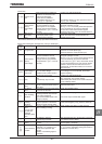
QR
Overvoltage
during fixed
speed operation
•Th
e input voltage fluctuates abnormally.
(1)The power supply has a capacity
of 500kVA or more.
(2)A power factor improvement
capacitor is opened and closed.
(3)A system using a thyrister is connected
to the same power distribution line.
•The motor is in a regenerative
state because the load causes the
motor to run at a frequency higher
than the inverter output frequency.
•The undervoltage detection level
H is too low.
•Insert a suitable input reactor.
•Install a dynamic braking resistor.
•Check the undervoltage detection level
H
.
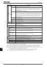
*QV Overtorque
•Overtorque reaches to a detection
level during operation.
•Stall prevention operation was
performed continuously for a
length of time longer than that set
with
H
.
•Check system error.
•Check whether the motor is overloaded or the
brake is engaged.
*WE Low current
•The output current decreased to a
low-current detection level during
operation.
•Check the suitable detection level for the system
(H).
•
Contact your Toshiba distributor if the setting is correct.
*WR
Voltage drop in
main circuit
•The input voltage (in the main
circuit) is too low.
•Momentary power failure occurs
because undervoltage continues
longer than undervoltage detection
time H.
•Check the input voltage.
•To cope with a momentary stop due to
undervoltage, enable WXE (Regenerative power
ride-through control), WX (auto-restart control),
and H (Undervoltage detection time).
*Presence or absence of parameter trip can be selected.
(Continued overleaf)