


E6581301
A-10
1
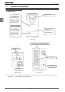
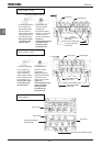
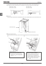
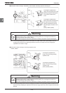
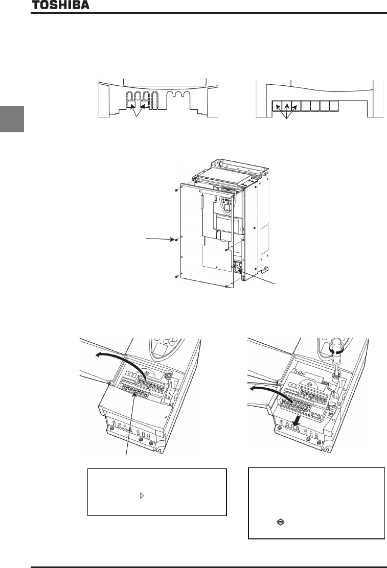
For 200V/0.4kW to 200V/15kW models and 400V/0.75kW to 400V/18.5kW models, cut off the tabs (part A in the
figure below) on the main circuit terminal cover if necessary for connecting the cables from the power supply.
200V-0.4kW
~
3.7/4.0kW
400V-0.75kW
~
3.7/4.0kW
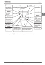
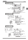
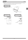
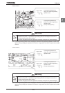
200V-5.5kW
~
15kW
400V-5.5kW
~
18.5kW
A
A
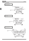
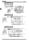
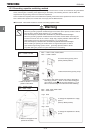
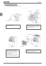
■ Front cover
To wire the main circuit terminal for models 200V-18.5kW or more and 400V-22kW or more, remove the front cover.
Main circuit terminal
Remove the screw
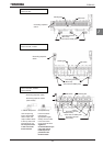
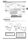
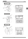
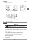
■ Control circuit terminal cover
To wire the control circuit terminal, open the control circuit terminal cover in line with the steps given below.
(A) (B)
(2)
(3)
Control circuit terminal
(1)
Open the control circuit terminal cover.
* To open the cover, lift it with your finger
placed at the
part on the right side of
the cover.
Remove the terminal, if necessary.
* To do so, open the main circuit terminal
cover, loosen the screws that fix the
terminal, using a (-) screwdriver or torx
(T20H) screwdriver, placed your finger on
part
and pull out the terminal.