


12-2
Cisco ASR 901 Series Aggregation Services Router Software Configuration Guide
OL-23826-09
Chapter 12 Configuring Resilient Ethernet Protocol
Understanding Resilient Ethernet Protocol (REP)
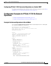
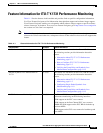
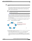
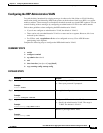
Figure 12-1 shows an example of a segment consisting of six ports spread across four switches. Ports E1
and E2 are configured as edge ports. When all ports are operational (as in the segment on the left), a
single port is blocked, shown by the diagonal line. When there is a network failure, as shown on the right
of the diagram, the blocked port returns to the forwarding state to minimize network disruption.
Figure 12-1 REP Open Segments
The segment shown in Figure 12-1 is an open segment; there is no connectivity between the two edge
ports. The REP segment cannot cause a bridging loop, and you can safely connect the segment edges to
any network. All hosts connected to switches inside the segment have two possible connections to the
rest of the network through the edge ports, but only one connection is accessible at any time. If a host
cannot access its usual gateway because of a failure, REP unblocks all ports to ensure that connectivity
is available through the other gateway.
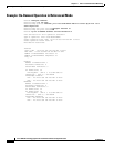
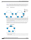
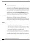
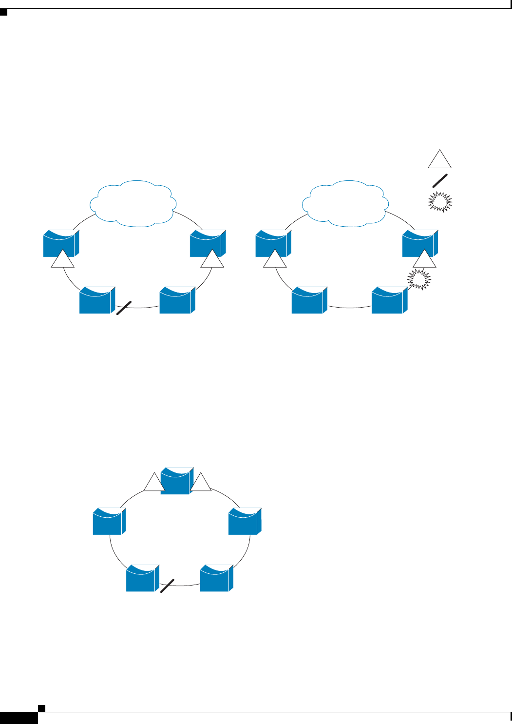
The segment shown in Figure 12-2, with both edge ports located on the same switch, is a ring segment.
In this configuration, there is connectivity between the edge ports through the segment. With this
configuration, you can create a redundant connection between any two switches in the segment.
Figure 12-2 REP Ring Segment
REP segments have these characteristics:
• If all ports in the segment are operational, one port (referred to as the alternate port) is in the blocked
state for each VLAN.
• If VLAN load balancing is configured, two ports in the segment control the blocked state of VLANs.
E2E1 E2E1
E1
Edge port
Blocked port
Link failure
201888
E2E1
201889