


22-44
Cisco ASR 901 Series Aggregation Services Router Software Configuration Guide
OL-23826-09
Chapter 22 Configuring Clocking
Configuring PTP for the Cisco ASR 901 Router
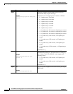
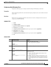
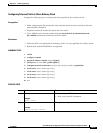
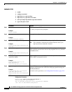
DETAILED STEPS
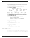
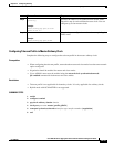
Verifying Telecom profile
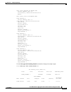
Use the show ptp port running detail command to display the details of PTP masters configured for a
Telecom profile slave. The PTSF and Alarm fields indicate the alarm experienced by the SLAVE clock
for the MASTER clock.
Router#show ptp port running detail
PORT [slave] CURRENT PTP MASTER PORT
Protocol Address: 208.1.1.3
Clock Identity: 0xE4:D3:F1:FF:FE:FF:BC:E4
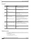
Command Purpose
Step 1
enable
Example:
Router> enable
Enables privileged EXEC mode.
• Enter your password if prompted.
Step 2
configure terminal
Example:
Router# configure terminal
Enters global configuration mode.
Step 3
ptp clock ordinary domain
domain
Example:
Router(config)# ptp clock ordinary
domain 4
Configures the PTP ordinary clock and enters clock
configuration mode.
• domain—The PTP clocking domain number. Valid
values are from 4 to 23.
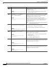
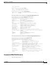
Step 4
clock-port
port-name
{master |
slave} [profile g8265.1]
Example:
Router(config-ptp-clk)# clock-port
Master master profile g8265.1
Sets the clock port to PTP master and enters clock port
configuration mode. In master mode, the port exchanges
timing packets with a PTP slave devices.
The profile keyword configures the clock to use the
G.8265.1 recommendations for establishing PTP sessions,
determining the best master clock, handling SSM, and
mapping PTP classes.
Note Using a telecom profile requires that the clock have
a domain number of 4–23.
Step 5
transport ipv4 unicast interface
interface-type interface-number
Example:
Router(config-ptp-port)# transport
ipv4 unicast interface loopback 0
Sets port transport parameters.
• interface-type—The type of the interface.
• interface-number—The number of the interface.
Step 6
end
Example:
Router(config-ptp-port)# end
Exits clock port configuration mode and enters privileged
EXEC mode.