


21-12
Cisco ASR 901 Series Aggregation Services Router Software Configuration Guide
OL-23826-09
Chapter 21 Configuring Pseudowire
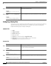
Configuring Pseudowire
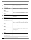
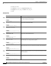
Step 4
encapsulation udp
Example:
Router(config-pw-class)#
encapsulation udp
Specifies the UDP transport protocol.
Step 5
ip local interface loopback
interface-number
Example:
Router(config-pw-class)# ip local
interface Loopback 1
Configures the IP address of the provider edge (PE) router interface as the
source IP address for sending tunneled packets.
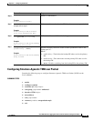
Step 6
ip tos value
value-number
Example:
Router(config-pw-class)# ip tos
value 100
Specifies the type of service (ToS) level for IP traffic in the pseudowire.
Step 7
ip ttl
number
Example:
Router(config-pw-class)# ip ttl 100
Specifies a value for the time-to-live (TTL) byte in the IP headers of Layer
2 tunneled packets.
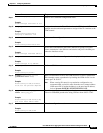
Step 8
controller {e1|t1}
slot/port
Example:
Router(config)# controller [e1|t1]
0/0
Enters E1/T1 controller configuration mode.
Step 9
cem-group
group-number
unframed
Example:
Router(config-controller)#
cem-group 4 unframed
Assigns channels on the T1 or E1 circuit to the CEM channel. This
example uses the unframed parameter to assign all the T1 timeslots to the
CEM channel.
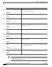
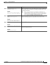
Step 10
exit
Example:
Router(config-controller)# exit
Exits controller configuration.
Step 11
interface cem
slot/port
Example:
Router(config)# interface CEM0/4
Selects the CEM interface where the CEM circuit (group) is located
(where slot/subslot is the SPA slot and subslot and port is the SPA port
where the interface exists).
Step 12
no ip address
Example:
Router(config)# no ip address
Disables the IP address configuration for the physical layer interface.
Step 13
cem
group-number
Example:
Router(config-if)# cem 4
Defines a CEM channel.
Command Purpose