


22-31
Cisco ASR 901 Series Aggregation Services Router Software Configuration Guide
OL-23826-09
Chapter 22 Configuring Clocking
Configuring PTP for the Cisco ASR 901 Router
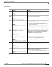
Current UTC Offset: 34
Leap 59: FALSE
Leap 61: FALSE
Time Traceable: FALSE
Frequency Traceable: FALSE
PTP Timescale: FALSE
Time Source: Internal Oscillator
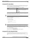
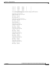
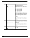
Verifying PTP Configuration on the 1588V2 Slave
The following examples help you verify the PTP configuration on the1588V2 slave.
Note The loopback interface assigned to PTP does not respond to ICMP pings. To check route availability,
either do it before assigning the interface to PTP, or remove PTP from the interface and then perform
ICMP ping. For removing PTP, use no transport ipv4 unicast interface loopback interface command.
Note The bridge state indicates the extension of previously known state which can be ignored or considered
to be normal. The clock state can get into holdover from bridge state when the packet delay variation is
high on the received PTP packets or the PTP connection is lost. This holdover state indicates that the
clock cannot be recovered from PTP packets as the quality is poor.
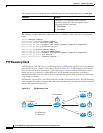
Example 1
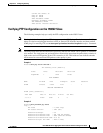
Router# show ptp clock runn dom 0
PTP Ordinary Clock [Domain 0]
State Ports Pkts sent Pkts rcvd
ACQUIRING 1 5308 27185
PORT SUMMARY
Name Tx Mode Role Transport State Sessions
SLAVE unicast slave Lo10 - 1
SESSION INFORMATION
SLAVE [L010] [Sessions 1]
Peer addr Pkts in Pkts out In Errs Out Errs
3.3.3.3 27185 5308 0 0
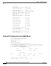
Example 2
Router# show platform ptp state
flag = 2
FLL State : 2 (Fast Loop)
FLL Status Duration : 7049 (sec)
Forward Flow Weight : 0.0
Forward Flow Transient-Free : 900 (900 sec Window)
Forward Flow Transient-Free : 3600 (3600 sec Window)
Forward Flow Transactions Used: 23.0 (%)
Forward Flow Oper. Min TDEV : 4254.0 (nsec)