


40-3
Cisco ASR 901 Series Aggregation Services Router Software Configuration Guide
OL-23826-09
Chapter 40 Digital Optical Monitoring
Examples
Examples
The real-time parameters of the router, such as optical output power, optical input power, temperature,
laser bias current, and transceiver supply voltage can be monitored using the
show interfaces transceiver command.
This section provides sample output for monitoring the real-time parameters on the ASR 901 router:
• Example: Displaying Transceiver Information, page 40-3
• Example: Displaying Detailed Transceiver Information, page 40-4
• Example: Displaying List of Supported Transceivers, page 40-5
• Example: Displaying Threshold Tables, page 40-6
• Example: Displaying Threshold Violations, page 40-9
• Example: Displaying Threshold Violations on a Specific Interface, page 40-9
• Example: When Transceiver Monitoring is Disabled, page 40-9
• Example: Displaying SPF Details, page 40-10
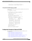
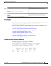
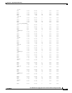
Example: Displaying Transceiver Information
This example shows how to display transceiver information:
Router# show interfaces transceiver
If device is externally calibrated, only calibrated values are printed.
++ : high alarm, + : high warning, - : low warning, -- : low alarm.
NA or N/A: not applicable, Tx: transmit, Rx: receive.
mA: milliamperes, dBm: decibels (milliwatts).
Optical Optical
Temperature Voltage Current Tx Power Rx Power
Port (Celsius) (Volts) (mA) (dBm) (dBm)
--------- ----------- ------- -------- -------- --------
Gi0/10 36.9 3.25 537.7 -4.5 -9.7
Gi0/11 35.8 3.22 393.6 -5.5 -5.0
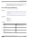
Step 4
monitoring
Example:
Router(config-xcvr-type)# monitoring
Enables monitoring of all optical transceivers.
Step 5
monitoring interval
seconds
Example:
Router(config-xcvr-type)# monitoring interval 500
(Optional) Specifies the time interval for monitoring
optical transceivers. Valid range is 300 to 3600
seconds, and the default value is 600 seconds.
Command Purpose