


39-3
Cisco ASR 901 Series Aggregation Services Router Software Configuration Guide
OL-23826-09
Chapter 39 Remote Loop-Free Alternate - Fast Reroute
Feature Overview
• The Border Gateway Protocol (BGP) Prefix-Independent Convergence (PIC) edge is not supported.
Specifically, the bgp additional-paths install command is not supported.
• If the network port is an LAG interface (etherchannel), you must use BFD over SVI to achieve FRR
convergence numbers.
• If the LAG interface is used either on access side or towards the core, you should shutdown the
interface before removing it.
Feature Overview
The LFA-FRR is a mechanism that provides local protection for unicast traffic in IP, MPLS, EoMPLS,
Inverse Multiplexing over ATM (IMA) over MPLS, Circuit Emulation Service over Packet Switched
Network (CESoPSN) over MPLS, and Structure-Agnostic Time Division Multiplexing over Packet
(SAToP) over MPLS networks. However, some topologies (such as the ring topology) require protection
that is not afforded by LFA-FRR alone. The Remote LFA-FRR feature is useful in such situations.
The Remote LFA-FRR extends the basic behavior of LFA-FRR to any topology. It forwards the traffic
around a failed node to a remote LFA that is more than one hop away.
In Remote LFA-FRR, a node dynamically computes its LFA node. After determining the alternate node
(which is non-directly connected), the node automatically establishes a directed Label Distribution
Protocol (LDP) session to the alternate node. The directed LDP session exchanges labels for the
particular forward error correction (FEC).
When the link fails, the node uses label stacking to tunnel the traffic to the remote LFA node, to forward
the traffic to the destination. All the label exchanges and tunneling to remote LFA node are dynamic in
nature and pre-provisioning is not required.
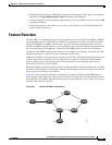
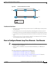
Figure 39-1 shows the repair path that is automatically created by the Remote LFA-FRR feature to
bypass looping. In this figure, the traffic is flowing between CE nodes (R1 to R7) through the PE nodes
(protected link - R2 and R3). When the PE node fails, the repair path (R2 - R4- R5 - R6 - R3) is used to
route the traffic between CE nodes.
Figure 39-1 Remote LFA-FRR Link Protection
303381
R7 R3
R2
R1
R4
R6
R5