


40-9
Cisco ASR 901 Series Aggregation Services Router Software Configuration Guide
OL-23826-09
Chapter 40 Digital Optical Monitoring
Examples
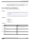
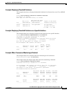
Example: Displaying Threshold Violations
This example shows how to display the threshold violations for all transceivers on a Cisco ASR 901
router:
Router# show interfaces transceiver threshold violations
Rx: Receive, Tx: Transmit.
DDDD: days, HH: hours, MM: minutes, SS: seconds
Time since Last Known
Time in slot Threshold Violation Type(s) of Last Known
Port (DDDD:HH:MM:SS) (DDDD:HH:MM:SS) Threshold Violation(s)
--------- --------------- ---------------------- ----------------------
Gi0/10 0000:02:50:19 Not applicable Not applicable
Gi0/11 0000:02:51:15 Rx power low alarm
-31.0 dBm < -17.1 dBm
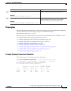
Example: Displaying Threshold Violations on a Specific Interface
This example shows how to display violations for the transceiver on a specific interface:
Router# show interfaces GigabitEthernet 0/9 transceiver
ITU Channel not available (Wavelength not available),
Transceiver is externally calibrated.
If device is externally calibrated, only calibrated values are printed.
++ : high alarm, + : high warning, - : low warning, -- : low alarm.
NA or N/A: not applicable, Tx: transmit, Rx: receive.
mA: milliamperes, dBm: decibels (milliwatts).
Optical Optical
Temperature Voltage Current Tx Power Rx Power
Port (Celsius) (Volts) (mA) (dBm) (dBm)
--------- ----------- ------- -------- -------- --------
Gi0/9 32.5 3.20 385.1 -5.5 -5.0
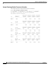
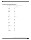
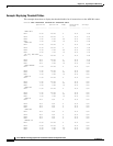
Example: When Transceiver Monitoring is Disabled
This example shows how to disable transceiver monitoring for all transceivers:
Router(config-xcvr-type)# no monitoring
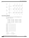
This example shows the sample output when transceiver monitoring is disabled:
Router# show interfaces transceiver detail
Transceiver monitoring is disabled for all interfaces.
mA: milliamperes, dBm: decibels (milliwatts), NA or N/A: not applicable.
++ : high alarm, + : high warning, - : low warning, -- : low alarm.
A2D readouts (if they differ), are reported in parentheses.
The threshold values are calibrated.
High Alarm High Warn Low Warn Low Alarm
Temperature Threshold Threshold Threshold Threshold
Port (Celsius) (Celsius) (Celsius) (Celsius) (Celsius)
--------- ----------------- ---------- --------- --------- ---------
Gi0/10 34.1 85.0 75.0 0.0 -5.0
Gi0/11 32.8 85.0 75.0 0.0 -5.0
High Alarm High Warn Low Warn Low Alarm
Voltage Threshold Threshold Threshold Threshold
Port (Volts) (Volts) (Volts) (Volts) (Volts)
--------- ----------------- ---------- --------- --------- ---------