


35-3
Cisco ASR 901 Series Aggregation Services Router Software Configuration Guide
OL-23826-09
Chapter 35 Layer 2 Control Protocol Peering, Forwarding, and Tunneling
How to Configure Layer 2 Control Protocol Peering, Forwarding, and Tunneling
• Spanning Tree Protocol (STP)—including Multiservice Transport Platform (MSTP) and Per VLAN
Spanning Tree (PVST)
• Virtual Trunking Protocol (VTP)
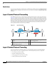
The ASR 901 router allows to tunnel layer 2 packets between CEs. The Cisco proprietary multicast
address (01-00-0c-cd-cd-d0) is used while tunneling the packet over the NNI interfaces.
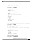
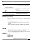
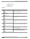
Figure 35-2 depicts Layer 2 Protocol Tunneling. The layer 2 traffic is sent through the S-network, and
the S-network switches the traffic from end to end. The Cisco multicast address is added to the frames
and sent from UNI to NNI. On the reverse path (NNI to UNI), protocol specific multicast address is
attached to the frames and sent to the UNI.
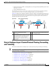
Figure 35-2 Layer 2 Protocol Tunneling
How to Configure Layer 2 Control Protocol Peering, Forwarding,
and Tunneling
This section describes how to configure layer 2 control protocol peering, forwarding and tunneling:
Note The configuration defined for LACP impacts all slow protocols, and is applicable to all the options like
peering, forwarding, and tunneling.
• Configuring Layer 2 Peering, page 35-4 (Required)
• Configuring Layer 2 Forwarding, page 35-5 (Required)
• Configuring Layer 2 Tunneling, page 35-7 (Required)
• Verifying Layer 2 Peering, page 35-9 (Optional)
• Verifying Layer 2 Forwarding, page 35-9 (Optional)
• Verifying Layer 2 Tunneling, page 35-9 (Optional)
1 2 3 2 1
334050
CE CE
ASR901
ASR901
PE
1 CE layer 2 control protocol tunnel
(end-to-end).
3 Third party PE forwards S-tagged frames and
peers untagged frames.
2 Cisco multicast address is added to the frames
and sent from UNI to NNI. On the reverse
path (NNI to UNI), a protocol specific
multicast address is attached to the frames and
sent to UNI.
4 —