


12-5
Cisco ASR 901 Series Aggregation Services Router Software Configuration Guide
OL-23826-09
Chapter 12 Configuring Resilient Ethernet Protocol
Understanding Resilient Ethernet Protocol (REP)
Note Use rep platform vld segment command on every Cisco ASR 901 router participating in the REP
segment.
• Enter the neighbor offset number of a port in the segment, which identifies the downstream neighbor
port of an edge port. The neighbor offset number range is –256 to +256; a value of 0 is invalid. The
primary edge port has an offset number of 1; positive numbers above 1 identify downstream
neighbors of the primary edge port. Negative numbers identify the secondary edge port (offset
number -1) and its downstream neighbors.
Note You configure offset numbers on the primary edge port by identifying the downstream position
from the primary (or secondary) edge port. Do not enter an offset value of 1 because that is the
offset number of the primary edge port.
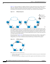
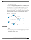
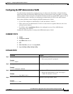
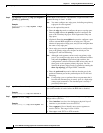
Figure 12-4 shows neighbor offset numbers for a segment where E1 is the primary edge port and E2
is the secondary edge port. The red numbers inside the ring are numbers offset from the primary
edge port; the black numbers outside the ring show the offset numbers from the secondary edge port.
Note that you can identify all ports (except the primary edge port) by either a positive offset number
(downstream position from the primary edge port) or a negative offset number (downstream position
from the secondary edge port). If E2 became the primary edge port, its offset number would then
be 1, and E1 would be -1.
• By entering the preferred keyword to select the port that you previously configured as the preferred
alternate port with the rep segment segment-id preferred interface configuration command.
Figure 12-4 Neighbor Offset Numbers in a Segment
When the REP segment is complete, all VLANs are blocked. When you configure VLAN load balancing,
you must also configure triggers in one of two ways:
• Manually trigger VLAN load balancing at any time by entering the rep preempt segment
segment-id privileged EXEC command on the router that has the primary edge port.
• Configure a preempt delay time by entering the rep preempt delay seconds interface configuration
command. After a link failure and recovery, VLAN load balancing begins after the configured
preemption time period elapses. Note that the delay timer restarts if another port fails before the time
elapses.
E2E1
-1
-2
-3
-4
-5
-6
-7
-8
-9
2
1
10
9
8
7
6
5
4
3
201890
E1 = Primary edge port
E2 = Secondary edge port
Offset numbers from the primary edge port
Offset numbers from the secondary edge
port (negative numbers)