


MODEL
8559A
ADJUSTMENTS
SECTION
V
ADJUSTMENTS
5-1. INTRODUCTION
5-2.
This section describes the adjustments used to
restore the
HP
8559A to its peak operating condition
after a repair or to compensate for changes resulting
from component aging. Illustrations showing the
appropriate test setups are included
in
the adjust
-
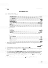
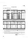
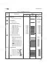
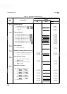
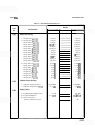
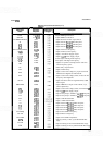
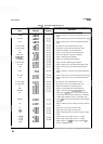
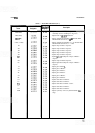
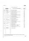
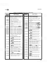
ment procedures. Table 5-1 lists all the adjustments
by adjustment name, adjustment reference designa-
tor, and by the paragraph number of the adjustment
procedure. Included in the table is a brief description
of the purpose of the adjustment.
5
-
3. Data taken during an adjustment should be
recorded in the spaces provided in the procedure.
Comparison of initial data with data taken during
later adjustments is useful for preventative mainte-
nance and troubleshooting.
The adjustments in this section
require the HP
8559A to be removed
from the display mainframe and con
-
nected through an extender cable
assembly. Be very careful; the energy
at some points in the instrument will,
if
contacted, cause personal injury.
The adjustments in this section
should be performed only by a skilled
person who knows the hazard
involved.
NOTE
Before performing any adjustments,
allow 1 hour
warmup time, unless 0th-
enrvise noted.
5
-
4. EQUIPMENT REQUIRED
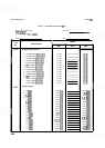
5-5.
Test equipment and accessories required for
the adjustment procedures are listed in Table
1
-
3.
If
the listed equipment is not available, substitute
equipment may be used provided it meets the mini
-
mum specifications given in the table.
5-6. Adjustment Tools
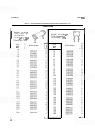
5-7.
Required service accessories, with part num-
bers, are illustrated in Section
I.
5
-
8. For adjustments that require a non
-
metallic
tuning tool, use fiber tuning tool,
HP
Part Number
8710
-
0033 (check digit
4).
When
a
non-metallic tun-
ing tool is not required, you may use an ordinary
small, flat-bladed screwdriver or other suitable tool.
Regardless of the tool used, do not try to force any
adjustment control. Slug
-
tuning inductors and varia-
ble capacitors, especially, are easily damaged by
excessive force.
5-9. Extender Cable Installation
1
WARNING
I
Disconnect display mainframe line
power cord before installation of
extender cable assembly.
5-10. Pull out the lock knob and slide the spectrum
analyzer out of the display mainframe. If side stops
are installed, refer to Section
I1 for removal.
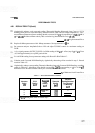
5-1 1. Carefully slide the extender cable assembly,
HP
Part Number 5060
-
0303, into the display main-
frame, aligning the metal guide plate with the slotted
side rails of the mainframe. Firmly seat the extender
cable assembly to ensure good contact.
5-12. Connect the opposite end of the cable to the
spectrum analyzer. The plug is keyed so it will go on
correctly and will not make contact upside down.
Remove the orange and the yellow leads from pins 3
and
4
on the A15 board at the rear of the spectrum
analyzer. Connect the corresponding leads from the
extender cable assembly to these pins by means of the
insulated alligator clips.