


MODEL
8559A
SERVICE
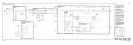
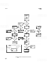
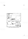
If the residual FM is unchanged, assume that the YTO Main Coil Fixed Driver is not its source. Retune the
HP
8559A to minimum, .010
GHz.
Isolate the YTO Main Coil Filter from the circuit by mounting the
Frequency Control Assembly A7 on an extender board and taping over
PI-19, PI-20, P1
-
25, while short
-
ing PI-2 to PI-19.
If the residual FM is unchanged, the probable source is the YIG
-
Tuned Oscillator Assembly A6.
If isolating the YTO Main Coil Tune Driver from the frequency control circuit eliminates the residual FM,
proceed to further isolate the source by shorting the sweep from block A to ground. This is best accom
-
plished by shorting the input side of R80 to the ground side of R63. Use a short jumper to prevent the
induction of line frequency noise into the circuit.
If the residual FM is eliminated, the source is probably the
FM/Main Coil Sweep Switch. The most
common failure is U15.
If residual FM is present after shorting the input sweep, remove the jumper and substitute a battery for the
tune voltage. Do this by carefully unsoldering the input side of R82 and inserting a battery
(5V to 10V)
between the free end of R82 (the
"
-
"
terminal) and the grounded end of R63 (the
"
+
"
terminal). Use the
shortest possible leads to prevent line frequency noise pickup.
If residual FM is unchanged, the probable source is the YTO Main Coil Tune Driver. The most common
failures are:
U10, R72, R76, R61, R80, R63, and R62, in that order.
In this step, the
-
10V regulator is replaced with a battery. Replace R82 and tape over P1
-
5. Attach the
negative
(
-
)
battery lead to pin 3 of U12; attach the positive
(+)
lead to the grounded end of R63. If the
residual FM is eliminated, the probable source is the
Tune/Full Span Voltage (block
B).
If the residual FM
is unchanged, remove the battery and the tape. Tune the FINE TUNE control to minimum, remover the
(945) wire from the COARSE TUNE control
(A2R1), and attach the battery's negative
(
-
)
lead to the
COARSE TUNE control in place of the (945) wire. Attach the positive
(+
)
battery lead to the ground side
of R63. This test is necessary to eliminate the TUNING control as
a
source of residual FM.
If using the battery in place of the
-
10V regulator eliminates residual FM, the
-
10V regulator is the
probable source. All of the regulator parts can cause instability; however, the most common failures are:
U7, R30, R33, R32, C3,
R29, and VR2 (block
H),
in that order. Also, verify that all supplies are properly
adjusted.
If the
Tune/Full Span Voltage (block
B)
is the probable source of the FM, the most common failures are
U12 and
413.
If isolating the YTO FM Coil Driver eliminates the residual FM, short the incoming sweep to ground.
Install a jumper between the input side of R97 and the ground side of R95. Use the shortest possible lead
to minimize line frequency noise pickup.
If the residual FM is unchanged, the source is probably the YTO FM Coil Driver. The most common
failures are U13 and U14.
If the residual FM is eliminated, the source is probably the
FM/Main Coil Sweep Switch. The most
common failure is U15. If the residual FM is unchanged, short
TP8 to ground. If this eliminates the
residual FM, the source is probably on the Marker Assembly
A8.
If isolating the YTO Main Coil Fixed Driver eliminates the residual FM, it is probably the source of the
FM. The most common failures are: U2,
C1, R1, and
R2,
in that order.
If removing the YTO Main Coil Filter from the circuit eliminates residual FM, it is probably the source of
the FM. The most common failure is Q5. If the FM is not eliminated, the most common failures are
A16Q1 and A16C22.
&711&72