


MODEL
8559A
SECTION Vlll
SERVICE
SERVICE
8-1.
INTRODUCTION
the listed instrument is not available, another instru-
ment that meets the required minimum specifications
8-2. This section provides instructions for trouble- may be substituted.
shooting and repairing the
HP
Model
855914
Spec
-
trum Analyzer.
It
includes circuit descriptions, gen-
eral servicing hints and information,
arts
identification iilustrations and lists, block diag;ams,
component locations diagrams, and schematics.
8
-
7.
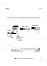
MAJOR ASSEMBLY LOCATIONS
To troubleshoot and repair this instru
-
ment, it must be removed from the
display mainframe and reconnected
through an extender cable. Operating
the spectrum analyzer outside the
mainframe in this manner exposes
high voltage points in the instrument
that will, if contacted, cause personal
injury. Maintenance and repair of this
instrument should, therefore, be per
-
formed only by a skilled person who
knows the hazards involved. Where
maintenance can be performed with
-
out power applied, the power should
be removed. When any repair is com
-
pleted, be sure that all safety features
are intact and functioning and that all
necessary parts are connected to
their positive grounds.
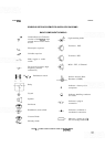
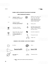
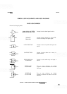
8-3. SCHEMATIC SYMBOLS, TERMINOLOGY,
AND VOLTAGE LEVELS
8-4.
Symbols and terminology used on the sche
-
matic diagrams are explained in Figure
8
-
1.
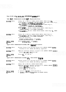
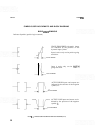
Test con
-
ditions for the signal and dc voltage levels shown on
the block and schematic diagrams are provided in
Figure 8-2.
8
-
5.
TEST EQUIPMENT
8
-
6.
Test instruments and accessories used to main-
tain the spectrum analyzer are listed in Table
1
-
4.
If
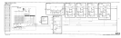
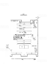
8-8. The major assembly location illustrations for
the spectrum analyzer are located near the end of this
section.
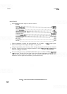
8-9.
TROUBLESHOOTING
8
-
10.
General Information
8
-
1
1.
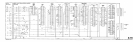
Troubleshooting is most easily accomplished
by using the block diagram at the end of this section
to follow the signal path. Once the problem is iso
-
lated to a particular circuit, the circuit description
and schematic diagram can be used to locate the
faulty component.
NOTE
When a part is replaced, adjustment
of the affected circuitry is usually
required. For adjustment procedures,
refer to Section
V.
Improper cleaning of the printed cir
-
cuit board edge connectors can
cause damage to the contact's gold
plating, resulting in corrosion and
intermittent electrical contact. Use
only the recommended procedure.