


SERVICE MODEL 8559A
Resistance R, is at a minimum (approximately 150 ohms) for small signals. The small signal gain of the stage
(about 10 dB) is established by the dc bias through the log diodes. As the signal level at the emitter of
413
increases, signal current cancels bias current in the log diodes, increasing R,. The gain of the stage for large
signals is reduced to unity
(0 dB) as R, becomes very large.
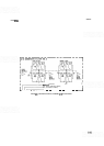
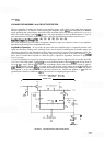
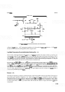
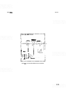
Linear Mode of Operation.
Two simplified schematics illustrating unity and 10 dB gain of a typical linear
stage are shown in Figures 8
-
65 and 8-66. In linear mode, the signal level dependent components are removed
from the signal path and a linear display is provided. The
-
8 VT is applied to the base of 424, turning it off.
This removes dc bias from
CRlO and CRll. Total resistance R, (primarily the resistance of R56 and CR12) is
high, since
CR12 is reverse
-
biased. Control line IFG6 is high and the stage gain is near unity. The signal flow is
through emitter follower
413 and R52, to 420. In stages six and seven, an alternate signal path is used to fix the
gain at about 5 dB per stage, allowing for scale differences between Log and Lin modes. Both stages are
activated by the
-
8 VT from the Amplitude Scale switch through R34, R93, R101, CR25, and CR28. The
combined stage gain is adjusted by R34 (LIN), which controls the dc PIN diode bias.
/
SECOND STAGE
\
OUT
LOGILIN LINE
-8VT
-@$
w4
FIGURE 8-65.
UNITY GAIN OPERATION IN LINEAR MODE, SlMPLlFlEDSCHEMATlC
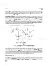
Stage 2, 3,4, and 5 each have an alternate signal path that switches in 10 dB of step gain for a total of
40
dB.
The alternate path is selected by the REFERENCE LEVEL control. With the INPUT
ATTEN at 0 dB and the
REFERENCE LEVEL control at
-68
dBm, the
-
8 VT is routed, via the IF gain control line (IFG4), to
forward bias CR22 in stage 5. For each stepped increase in the REFERENCE LEVEL control, the
-
8 VT
activates the IFG lines associated with the stages of gain required, forward biasing the diodes in the signal path.
Each IFG line has a potentiometer (block B) that controls the
line's bias current and the stage gain. Note that
IFG6 controls two stages (stages
2
and 3) that, when switched in, provide 20 dB of gain.
Gain Control Lines
(B)
The
+
15V (in Log mode) or the
-
8 VT (in Lin mode) is routed through the REFERENCE LEVEL switch to
the combination of
IFG4, IFG5, and IFG6 corresponding to the reference level selected. In Log mode, the Log
Offset circuit is activated through
R24,
R25, and R26. The LOG/LIN line is at
+
15V, 424 is saturated, and the
0-1
68