


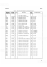
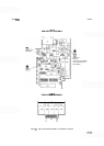


SERVICE MODEL
8559A
Display Interface
(E)
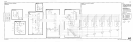
During the period the DPM drive input is being converted, the BCD output circuitry in U3 is shut off. Once the
conversion in U2 and U3 is complete, the four-line BCD is sent to U4 where it is converted to a seven-line
(segment) drive. This seven-line output from U4 is fed in parallel to the displays on the Display Assembly A1
A1
.
Coincident with the BCD-to-seven-segment conversion, U3 supplies a digit strobe drive that, by turning on one
of the DPM Display Assembly
A1 A1 transistors (AlAlQl- A1 AlQS), activates one of the seven-segment
displays.
Multiplexed BCD data from the digital processor IC (U3) are level shifted by transistors
43, 44, Q5, and 46
and decoded by the BCD-to-seven-segment decoder-driver IC, U4. The decoder-driver sinks the current that
drives the paralleled LED display segments on the
DPM
Display Assembly AlAl. The digit strobe outputs from
U3 are level shifted by
47, A1 1, A12, 413, and 414 and subsequently drive the Darlington
-
transistor switches
A1 AlQl through A1Al Q5 on the DPM Display Assembly A1A 1.
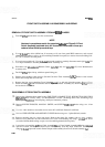
DIGITAL PANEL METER ASSEMBLY Al, TROUBLESHOOTING
Check supply and reference voltages first.
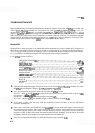
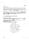
Display digits freeze intermittently:
Be sure the clock oscillator signal goes at least
-
7V negative and
appears as in Figure 8-4. Low gain (Gm) of
AlA2Q8 is the most probable cause for failure. Resistor AlA2Rl is
factory selectable; increasing its value increases the amplitude of the clock output,
Least Significant Digit (LSD) dithers:
AlA2U2 is the most probable cause; however, noise from
AlA2R24, AlA2R25, or AlA2C5 also causes this symptom.
The same segment in each digit does not light:
AlA2U4 failure.
FIGURE
8-4.
DPM CLOCK OUTPUT