


ADJUSTMENTS
MODEL
8559A
ADJUSTMENTS
5
-
22. 3
-
dB BANDWIDTH ADJUSTMENTS (Cont'd)
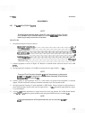
Adjust A9R72
XTL
to bring signal level to the fifth graticule line (three divisions from the top graticule
line).
Increase signal generator frequency until signal on CRT display peaks and then decreases to the fifth
graticule line. Record counter frequency.
Compare new frequency
should be 2800 to 3200
readjusting
A9R72 XTL,
with frequency recorded in step 14. The difference between the two frequencies
Hz. If the bandwidth is not within limits, repeat steps
12
through
17,
slightly
until the specified limits are achieved.
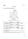
Set RESOLUTION BW to 10 kHz. Tune signal generator to peak signal on CRT display.
Adjust REF LEVEL FINE to place signal at
7.1
divisions.
Decrease signal generator frequency until the signal on the CRT display is at the fifth graticule line. Record
this frequency.
Increase the signal generator frequency until the signal on the CRT display peaks and then decreases to the
fifth graticule line. Record this frequency.
Compare new frequency with frequency recorded in step 20. The difference between the two frequencies
should be
9.000 kHz to 11.000 kHz.
NOTE
A9R72 XTL may be further adjusted to bring the 10 kHz and
1
kHz band
-
widths within limits; however, the final measurement of the 3 kHz bandwidth
must be between 2700 Hz and 3300 Hz. (If the 10 kHz bandwidth cannot be
brought within limits by adjusting
A9R72 XTL, change the value of factory
-
selected resistor A9R111*. If the
1
kHz bandwidth cannot be brought within
limits by adjusting
A9R72 XTL, change the value of A9R109*.)
Set RESOLUTION BW to
1
kHz. Tune signal generator to peak signal on CRT display.
Adjust REF LEVEL FINE to place signal at 7.1 divisions.
Record the counter frequency.