


ADJUSTMENTS
MODEL
8559A
ADJUSTMENTS
5
-
27. THIRD CONVERTER ADJUSTMENTS (Cont'd)
Adjust function generator amplitude and frequency for at least 10 MHz deviation
(k
5 MHz) and an easy-
to
-
view display on the 8569B spectrum analyzer. Refer to Figure 5-15. Increasing the frequency of the
function generator will increase the swept frequency range of the sweep oscillator.
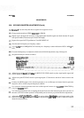
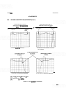
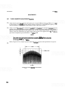
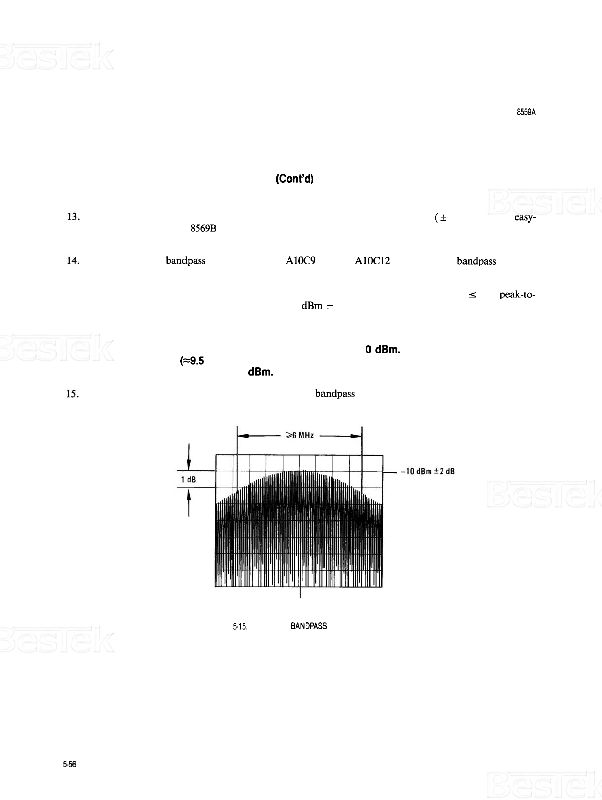
Adjust second IF
bandpass filter adjustments A10C9 through A10C12 for the flattest bandpass response
possible at the greatest amplitude possible centered at 21.4 MHz and at least 6 MHz (6 divisions) wide at 1
dB down from the highest point on the response curve. Do not sacrifice large amounts of amplitude for
flatness. Some early instruments may display ripple on the response. This ripple should be
I
1 dB peak-to-
peak. Peak of adjusted response should be at
-
10 dBm
+
2 dB.
NOTE
The output level of the third converter is actually
0 dBm. Due to the mis
-
match error (~9.5 dB) encountered in this measurement, the level measured
will be approximately
-
10
dBm.
Refer to Figure 5-15 for example of properly adjusted bandpass response and requirements for response.
21.4
MHz
FIGURE
5-15,
SECOND IF BANDPASS FILTER RESPONSE