


MODEL 8559A ADJUSTMENTS
ADJUSTMENTS
5
-
22. 3
-
dB BANDWIDTH ADJUSTMENTS (Cont'd)
NOTE
If the 100
kHz
bandwidth is not within the specified limits, change the
values of factory
-
selected resistors A11R19*, A11R43*, A13R19*, and
A13R43*. If the bandwidth is too wide, increase the value of the resistors; if
the bandwidth is too narrow, decrease the value of the resistors. The fac
-
tory
-
selected resistors need not be of equal value, but each must be within
one standard value of the others.
8.
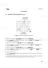
Set RESOLUTION BW to 30 kHz and FREQ
SPAN/DIV to 10 kHz. If necessary, reset signal level with
REF LEVEL FINE control. The bandwidth should be between 2.6 and 3.4 divisions at the fifth graticule
line.
NOTE
If the 30
kHz
bandwidth is not within the specified limits, change the values
of factory
-
selected resistors A1
1
R23*, A1 1 R48*, A13R23*, and A13R48*. If
the bandwidth is too wide, decrease the value of the factory
-
selected resis
-
tors; if the bandwidth is too narrow, increase the value of the resistors. The
factory
-
selected resistors must be within three standard values of the nomi
-
nal value.
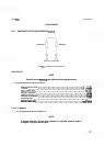
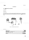
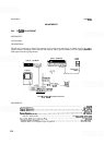
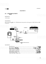
9. Connect signal generator as shown in Figure 5
-
8. Tune signal generator to approximately 21.4 MHz. Set
the signal generator to approximately
0 dBm and the step attenuator to 10 dB. Set COUNTER MODE to
EXPAND
X 100.
10. Place spectrum
analyLer on right side and connect test cable to Third Converter 21.4 MHz output connec-
tor
A16J3. If connector is not present (some early instruments were not so supplied), remove AlOWl from
A5J2 and connect AlOWl through a 10 dB step attenuator set to 30 dB and the signal generator set for a
-
10 dBm output level. The 10 dB step attenuator between BNC tee and frequency counter can be elirni-
nated.
11. Set HP
8559A RESOLUTION BW to
1
MHz. Tune signal generator to peak signal on CRT display (near
21.4 MHz)
(321.4 MHz if injecting into AlOWl). Adjust the output level of signal generator to place the
signal at 7.1 divisions.
12. Set RESOLUTION BW to 3 kHz. Tune signal generator to peak signal on CRT display.
13. Adjust REF LEVEL FINE to place signal at 7.1 divisions.
14. Note the counter frequency and tune the signal generator 1500 Hz below the center frequency noted.
Record the new counter frequency.