


MODEL 8559A ADJUSTMENTS
ADJUSTMENTS
5
-
28.
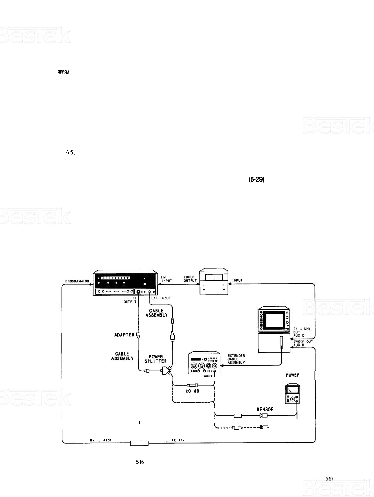
FREQUENCY RESPONSE ADJUSTMENTS
REFERENCE:
A3, A4,
AS, A6, and A12 Schematics
NOTE
Perform CAL OUTPUT and REF LEVEL CAL adjustments
(5-29)
before pro
-
ceeding with frequency response adjustments.
DESCRIPTION:
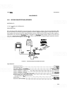
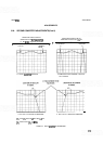
Frequency Response (flatness) is adjusted in six parts corresponding to the
six
harmonic bands of the analyzer.
In each band, the analyzer is swept
-
tuned with a tracking signal source comprising a sweep oscillator and
synchronizer. The sweep oscillator is tuned with an external sweep ramp generated by scaling the analyzer sweep
output (AUX D) with a special tuning voltage circuit. This provides synchronization of the sweeps of the two
instruments (sweep oscillator and analyzer), thus providing phase
-
lock of the two instruments. Each of the
bands is adjusted for optimum flatness and all bands are adjusted for equal amplitudes.
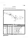
SWEEP RF
OSCILLATOR PLUG
-
IN SYNCHRONIZER
Dl SPLAY
ASSEMBLY
CRYSTAL
1
1
DETECTOR
ADAPTER
1
SPECTRUM
ANALYZER
0000
o...
ADAPTER
METER
I
ATTENUATOR
'
L
- - - -
-
- -
-
- - -
4
POWER
!
ADAPTER SENSOR
TUN
l
NG
VOLTAGE
CIRCUIT
I
L----
-----
0
-
---
-
--
ADAPTER POWER
J
(FIGURE
5
-
17)
OV
TO
t10V
-
-
5V
TO
+5V
SENSOR
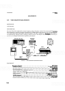
FIGURE
5-16,
FREQUENCY RESPONSE ADJUSTMENTS TESTSETUP