


MODEL
8559A ADJUSTMENTS
ADJUSTMENTS
5
-
26.
SECOND CONVERTER ADJUSTMENTS (Cont'd)
nrn ALT IF on and verify that the two signals do not appear to move.
Change spectrum analyzer FREQ
SPAN/DIV to 500 kHz.
Repeat steps 7 through 14 if necessary to align both signal identifier signals and both alternate IF signals
and spaced 1 MHz
(2
divisions) apart on the CRT display.
Depress front
-
panel ALT IF pushbutton. Turn SIG IDENT off.
Note Second LO frequency on frequency counter.
Adjust
A5Z4 2nd LO FREQUENCY if necessary for a frequency counter indication of 2671.1 MHz
+
0.5
MHz.
If second LO frequency is readjusted, recheck second LO shift adjustments, steps 5 through 16.
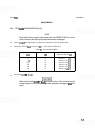
Set spectrum analyzer controls as follows:
..........................................................
FREQSPAN/DIV 2MHz
..................................................................
RESBW 3MHz
............................................................
REFLEVELdBm
-
10
.............................................................
INPUTATTEN 10dB
.........................................................
Amplitudescale ldB/DIV
................................................................
TIME/DIV AUTO
FREQUENCYBANDGHz
...........................................
Band1 (.01-3)
......................................................................
ALTIF ON
SIG IDENT
.................................................................
OFF
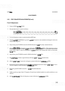
Adjust front
-
panel REF LEVEL dBm and REF LEVEL FINE controls to place signal peak in upper half
of CRT display for convenient viewing.
Adjust front
-
panel TUNING control to place signal peak 3.75 divisions to the left of center screen on the
CRT.
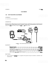
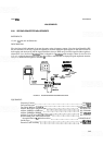
Connect the HIGH output of the function generator to an oscilloscope and adjust function generator
output for a OV to
+
20V ramp and frequency to 500 Hz.
Disconnect the function generator from the oscilloscope and connect it to
A5A2TP1 VARACTOR by
using the
8
120- 1292 adapter.
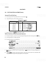
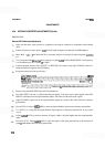
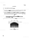
The following adjustments refer to aligning the Second Converter after internal repair of the converter. If
the entire converter has been replaced, it will probably not be necessary to perform
all
of the adjustments.
Adjustments
A5Z1, A5Z2, A5Z3, and A5L2 are used to align the bandpass filter and output match of the
Second Converter.
Z1 and L2 are used to adjust amplitude and 22 and 23 are used to center the response
about the center frequency.