


/
-
ADJUSTMENTS
5
-
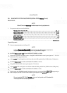
22.
3
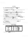
dB BANDWIDTH ADJUSTMENTS (SERIAL PREFIX 1909A) (Cont'd)
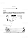
10. Remove AlOWl from A5J2 2nd CONV OUT Connect step attenuator through adapter to A1OW 1.
11.
Set
HP 8559A RESOLUTION BW to
1
MHz. Adjust the output level of signal generator to place the
signal near center graticule line. Tune signal generator frequency to peak signal on
oscillo~cope display
(near 321.4 MHz).
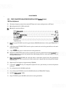
12.
Set
RESOLUTION BW to 3 kHz. Tune signal generator to peak signal on oscilloscope display.
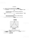
13, Adjust output level of signal generator to place signal at 7.1 divisions.
14. Note the counter frequency and tune the signal generator
1500 Hz below the center frequency noted.
Record the new counter frequency.
MHz
15. Adjust
A9R72 XTL to bring signal level to the fifth graticule line (three divisions from the top graticule
line).
16.
Increase signal generator frequency until signal on oscilloscope display peaks and then decreases to the
fifth graticule line. Record counter frequency.
MHz
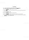
17. Compare new frequency with frequency recorded in step 14. The difference
between
the two frequencies
should be 2800 to 3200 Hz. If the bandwidth is not within limits, repeat steps 12 through 17, slightly
readjusting
A9R72 XTL, until the specified limits are achieved.
18. Set RESOLUTION BW to 10 kHz. Tune signal generator to
peak
signal on oscilloscope display.
19. Adjust REF LEVEL FINE to place signal at 7.1 divisions.
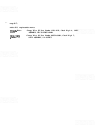
24).
Decrease the signal generator frequency until the signal on the oscilloscope display drops to the fifth
graticule line. Record counter frequency.
MHz
21.
Increase the signal generator frequency until the signal on the oscilloscope display peaks and then
decreases to the fifth graticule line. Record counter frequency.
MHz