


MODEL
8559A
ADJUSTMENTS
ADJUSTMENTS
5
-
23. RF GAIN ADJUSTMENT (Cont'd)
NOTE
To make special extender board, solder 51.1 ohm resistor from pin 18 to pin
22 of standard
24
pin extender board, HP Part No. 5060-0258. Leave resistor
leads long for easy connection of clip leads.
PROCEDURE:
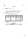
1. Set spectrum analyzer controls as follows:
FREQUENCYBANDGHz
..................................................
.01-3
FREQ SPAN/DIV
..........................................................
1 MHz
RESOLUTIONBW
.........................................................
lMHz
INPUTATTEN
..............................................................
OdB
REFLEVELdBm
............................................................
-
10
REFLEVELFINE
..............................................................
0
Amplitudescale
..............................................................
LIN
SWEEP
TIMWDIV
........................................................
AUTO
SWEEPTRIGGER
.....................................................
FREERUN
VIDEOFILTER
.............................................................
MIN
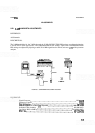
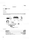
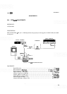
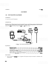
2.
Connect equipment as shown in Figure 5
-
9. Resistor on extender board should be toward rear of
HP
8559A.
3.
Set signal generator frequency to
21.4
MHz. Set output level for approximately
-
5 dBm.
NOTE
To remove Third Converter Assembly
A10, it will be necessary to disconnect
A1OW1 from A5J2 and temporarily remove Marker Assembly A8 and Sweep
GeneratorlRes BW Assembly A9.
4.
Connect output of signal generator across 51.1 ohm resistor on special board using BNC to clip
-
lead
adapter. The red lead (center conductor) should be connected to pin 18 of extender board.
5. Set signal generator frequency for peak amplitude on CRT display. Connect output of signal generator to
power meter through a power sensor and set output level to
-
3
dBm. Reconnect signal generator output
to clip
-
lead adapter.
6.
Adjust A12R5 GAIN adjustment for signal one division from top graticule line. DVM should indicate
+
700
mV
+
30
mV. Remove special extender board and replace Third Converter Assembly A10.
NOTE
If step gain adjustments will be performed next, do not reconnect
A1OW1 to
A5J2.