


MODEL
8559A
SERVICE
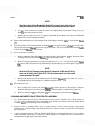
14.
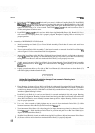
Disconnect 10-conductor ribbon cable connected to DPM Driver Assembly
AlA2. Remove screw holding
DPM Display Assembly
AlAl to diecast. DPM window will fall out.
15. Use a
5/16-inch nut driver to remove the two nuts attaching front panel to Front Switch Diecast (1).
Remove front panel from Front Switch
Diecast.
16.
Place Front Switch Assembly A2 on flat working surface with remaining knobs face-down and lock
mechanism facing you. Prop sides of switch assembly to allow knobs and shafts to clear working surface
(be careful not to scratch front panel enamel).
17. Remove screw and washer attaching Attenuator Bracket (49) to Front Switch
Diecast (1). Remove RF
Input Attenuator Assembly A3 from Front Switch Assembly
A2.
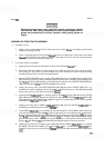
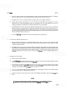
18. Disassembly of REFERENCE LEVEL Switch:
Cut
tiewrap holding REF LEVEL FINE wires to rear switch board.
Remove the three screws (48) attaching Ref Level Fine Pot Plate (68) to Standoffs (62).
Remove Index Disc Locator and Ref Level Fine assembly
(30, 31, and
64
through 69) from Front
Switch Assembly A2 (set to one side, without detaching wires).
Remove three standoffs (62) used to support Ref Level Fine Pot Plate (68). Use a no. 6 hex wrench to
loosen the two set screws on Miter Gear (51) attached to Attenuator Shaft Assembly (18); then
remove Miter Gear from shaft.
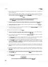
Use a no. 4 hex wrench to loosen Rotating Lockout (63) attached to Ref Level Shaft
(6), and remove
lockout from shaft. Remove Ref Level Detent (61) from Front Switch Assembly
A2. Be careful to
keep Ball Bearing (10) and Spring
(1
1)
with Ref Level Rotor (60).
Remove the three Studs (53) used to support Ref Level Detent (61).
Use a no. 4 hex wrench to loosen the two set screws on front Anticrush Drive Hub Assembly
(7)
(between Front Switch Board MA1 and Front Switch Diecast (1) on Ref Level Shaft (6); accessible
from side of Front Switch Assembly). Remove Ref Level Rotor (60) and Ref Level Shaft (6) with rear
Anticrush Drive Hub Assembly (7) still attached.
NOTE
Rear Anticrush Drive Hub Assembly (7) on Ref Level Shaft
(6)
is preset at
9.525
mm
(0.3
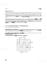
in.) from end of shaft (see Figure 8-7A). Do not remove drive
hub unless necessary for repair.
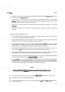
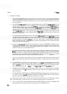
19. Disassembly of RESOLUTION BW Switch.
a. Remove Retaining Clip (21) from RESOLUTION BW Shaft (55).
b. Use a
1/4-inch Nut Driver to remove two Hex Nuts (20) attaching Bandwith Switch Board (59) to
Front Switch Assembly, and set board to one side (without detaching wires).
c.
Remove Bandwidth Rotor (56). Be careful to keep Ball Bearings (10) and Springs (23) with rotor.
d.
Remove Bandwidth Shaft
(55), with rear Drive Hub (15) still attached, from Front Switch Assembly.
827