


MODEL 8559A SERVICE
to the Pulse Shaper. Resistor A16R2 and capacitor A16C8 on the motherboard attenuate the ac line signal to
approximately
1V peak-to-peak (at the base of 435) and filter line spikes.
Single Sweep Triggering and
Abort
When the TRIGGER switch is in the single sweep position, the sync line is grounded and the single line open.
Transistor 433 is held off by the voltage developed across
CRlO and R53. The voltage at the collector of 433 is
at
+
10V, putting the emitter of 438 at
+
9.4V This charges C15 to
+
2.4V through voltage divider R48 and
R49.
A sweep is initiated when the trigger switch is set to the spring-loaded SINGLE position and
+
15V is applied to
the single trigger switch (block
N).
When 437 turns on, a negative pulse is produced at the emitter of 433 due to
voltage stored by C15. This pulse turns 433 on and starts the sweep cycle.
The sweep may be aborted (reset to
-
5V) by pressing the single sweep switch while the sweep is in progress.
During the sweep, the collector of 433 is at
+
0.5V This puts the emitter of 438 at OV and charges C15 to
-
4V
through voltage divider R48 and R49. Now when
+
15V is applied to the single trigger switch (block
N),
437
turns on and a positive pulse appears at the emitter of 433. Consequently, 433 turns off and the sweep is
aborted.
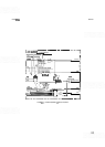
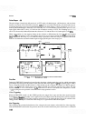
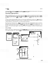
Manual Sweep
Manual sweep control is obtained when the SWEEP TIME/DIV switch is set to MAN. In the manual position,
ST7 is open (see Figure 8
-
37). Transistor 440 turns 433 on by supplying current to its base and 439 acts as a
-
BUFFER
AMPL
IF
l
01 ,Q3,Q4
,,,,,
@
COMPARATOR
-n
@
RETRACE
I
OUT BUFFER
1
AMPLIFIER
+i4v
0
MANUAL SWEEP
15v
MAN
CONTROL
P
t15V
ST7
0
,
t15V
DURING
MANUAL
SWEFP
R36
CR3
FIGURE
837.
MANUALSWEEP MODE, SIMPLIFIED SCHEMATIC