


MODEL 8559A
SERVICE
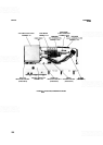
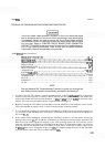
RESIDUAL
FM
TROUBLESHOOTING FLOWCHART ANNOTATION
In the next steps, edge connector contacts on the circuit board are taped
over to isolate portions of the circuit. After completing a step where taping
is necessary, remove the tape and clean the circuit board edge contacts
with an
80120
solution of isopropyl alcohol and water before continuing to
the next step. Refer to PRINTED CIRCUIT BOARD EDGE CONNECTOR
CONTACT CLEANING at the beginning of this section for a detailed descrip
-
tion of the cleaning procedure. Care should also be taken whenever
instructed to unsolder components during the test.
Set HP 8559A controls as follows:
..................................................
FREQUENCYBANDGHz .01-3
TUNING
...............................................................
.010 GHz
FREQSPAN/DIV
...............................................................
0
.......................................................
RESOLUTIONBW 300kHz
..............................................................
INPUTATTEN OdB
REFERENCE LEVEL
.....................................................
-
10 dB
..............................................................
REFLEVELFINE 0
Amplitude Scale
........................................................
10 dB/DIV
SWEEP TIME/DIV
........................................................
AUTO
SWEEP TRIGGER
.......................................................
SINGLE
.............................................................
VIDEOFILTER OFF
....................................................................
BLCLIP OFF
.................................................................
SIGIDENT OFF
.....................................................................
ALTIF OFF
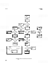
NOTE
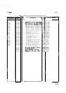
Use the Residual FM Troubleshooting Flowchart to guide you through the
test. Refer to this annotation as indicated by the steps in the flowchart.
a. To observe the first LO, connect a second spectrum analyzer to the HP 8559A
RF
input (a significant
fraction of the first LO power is coupled to the RF input by the First Mixer Assembly A4). When mea
-
sured in this manner, the first LO power should be
-
8 dBm
t
3 dBm at about 3 GHz for the listed control
settings. This setup is used to observe the first LO in all of the following tests.
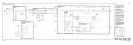
b. Begin by isolating the YTO Main Coil Tune Driver from the remainder of the frequency control circuit.
This is accomplished by taping over P1
-
3 on the circuit board edge
-
connector contacts.
c.
If the residual FM is unchanged, assume that the YTO Main Coil Tune Driver and the circuits feeding it are
not the source of FM. The next step is to isolate the YTO FM Coil Driver from the circuit by taping over
PI
-
15 and PI-37.
d. If the residual FM is unchanged, assume that the YTO FM Coil Driver is not the source. Proceed by
placing a short across
C1. This isolates the YTO Main Coil Fixed Driver from the circuit. Since the YTO
Main Coil Fixed Driver supplies the majority of the YTO operating current, the YTO will not operate
when the YTO Main Coil Fixed Driver is isolated from the circuit. To compensate for this, it is necessary
to increase the current supplied by the YTO Main Coil Tune Driver. Adjust the TUNING control of the
HP
8559A under test for a frequency display of 3 GHz; this supplies enough current from the YTO Main
Coil Tune Driver to allow the YTO to oscillate at about 3
GHz.