


ADJUSTMENTS
MODEL
8559A
ADJUSTMENTS
5
-
24.
STEP GAIN ADJUSTMENTS
(Cont'd)
PROCEDURE:
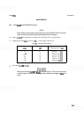
Set spectrum analyzer controls
as
follows:
FREQSPAN/DIV
..........................................................
lMHz
.........................................................
RESOLUTIONBW lMHz
INPUTATTEN
.............................................................
10dB
...............................................................
REFLEVELdBm 0
Amplitudescale
.........................................................
ldB/DIV
........................................................
SWEEPTIME/DIV AUTO
.....................................................
SWEEPTRIGGER FREERUN
VIDEO FILTER
.............................................................
MIN
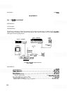
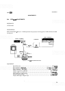
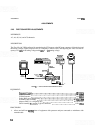
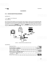
Connect equipment as shown in Figure 5
-
10. Connect signal generator tuned to 321.4 MHz with approxi
-
mately
-
30 dBm output to one side of a 1 dB/step attenuator. Connect step attenuator output to AlOWl
through adapter. Tune signal generator frequency for peak amplitude on display.
Set step attenuator to 12 dB and REF LEVEL FINE to
-
12. Set signal generator level for a signal one
division down from top graticule line.
Adjust
A12R39
-
12 D until signal stops rising on display, then adjust A12R39 counterclockwise until
signal drops approximately one third to one half of a division.
Set signal generator level so signal is one division down from top graticule line on display.
Set step attenuator to
0 dB and REF LEVEL FINE to 0.
Adjust A12R35 0 D adjustment for a signal level one division from top graticule line.
Set step attenuator to 12 dB and REF LEVEL FINE to
-
12. DVM indication should be
700
+
30 mV
(offset). If offset is greater than
+
30 mV, repeat steps 3 through
8
until DVM indication is within limits.
Replace 1
dB/step attenuator with 10 dB/step attenuator set to 0 dB. Set REF LEVEL FINE control to 0.
Tune signal generator frequency for peak amplitude on the display (near 321.4 MHz).
Set signal generator level for a signal one division down from top graticule line. Set step attenuator to 10
dB and REF LEVEL
dBm to
-
10.
Adjust
A12R6 10 D adjustment for signal level one division from top graticule line.
Set step attenuator to 20 dB and REF LEVEL
dBm to
-
20.
Adjust
A12R21 20 D adjustment for signal level one division from top graticule line.
Set attenuator to
40
dB and REF LEVEL dBm to
-
40.