


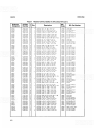


SERVICE
MODEL
8559A
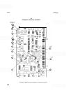
Second LO Driver
(E)
The Second LO Driver varies the voltage applied to the varactors in the second LO cavity (A5CR2 and A5CR3).
The upper limit of this voltage is dependent on the second LO sensitivity and varies during operation from
about
I
V to between 7V and 30V. An increase in the drive voltage increases the second LO frequency. The SIG
IDENT and ALT IF buttons both change the second LO frequency.
ALT
IF.
When ALT IF is not selected, TP2 is at -7.5Y setting the collector of 42 to
+
15V
(f
7V). When
ALT IF is selected, TP2 goes to
-
2.5% setting the base of 42 to about
+
5V. The voltage on the collector of 42
varies within the range of 1V to 28V as needed to drive the varactors in the Second Converter Assembly A5. The
shift in drive voltage serves to offset the second LO to the alternate IF.
SIG IDENT.
When SIG IDENT is not selected, U10 pin 4 is low and pin 11 is high. This supplies a current
through R37 and R38 to bias the second LO
1 MHz away from its minimum frequency. When SIG IDENT is
selected, pins 4 and 11 both are either high or low together, depending on the sense of the PM line (PM is low
for bands
1,
3, and 5). This either raises or lowers the frequency of the second LO 1 MHz. Resistor R39
provides additional shift, if necessary, when ALT
IF
is not activated (the second LO may be less sensitive at that
frequency). Flip
-
flop U3 alternates both the frequency shift and level shift on every other retrace.
Auto Scan Time (AST) Drivers
(C)
As scan and bands change, sweep times must be changed to maintain amplitude calibration. The AST (auto
scan time) line, which goes to the Sweep
Generator/Bandwidth Control Assembly A9, varies the sweep time by
varying the amount of current it carries. More current speeds the sweep rate, less current slows it. The current is
controlled through a current mirror on the Marker Assembly
A8, comprising U6a and U6d. The current mirror
is
a
common
-
emitter amplifier with a current gain of
-
1.
Collector current changes through U6a (caused by
Ul
1
a, U11 b, or
U
l lc turning on) are mirrored in U6d.
Scan Attenuator (B)
Operational amplifiers U13 and U17 are buffer amplifiers that are not directly involved in the switchable scan
attenuation, but, if one fails, the scan becomes uncalibrated. The switching is done by
44, Q6, and U12. For
fundamental mixing bands
1
and 2, U12b is on, all others are off. Resistors R22 and R23 form a voltage divider
with R24, R25, and R26. The division ratio is changed depending on whether
44 and 46 are on or off. For
higher mixing modes (bands 3 through 6),
U12a or U12d is switched on, picking off the sweep from a lower
amplitude point on the voltage divider. For full span operation,
U12c is enabled so that no attenuation is added
for higher mixing modes.
MARKER ASSEMBLY A8, TROUBLESHOOTING
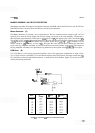
DPM Accuracy:
DPM inaccuracy is often traceable to the calibrated
-
gain circuit in the DPM Driver (block
D). The most common cause is the gain determining resistors associated with U15.
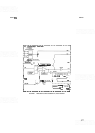
A
generalized model of U15,
with associated resistors, is shown as Figure 8
-
30. Variations in the input resistors or in the feedback resistors
will cause DPM inaccuracies throughout its range. Offset resistor variations primarily affect the low end of the
range. When troubleshooting DPM inaccuracies, always start with the components related to the worst band.
Marker Accuracy:
The marker accuracy is dependent on the frequency accuracy of the first LO and the
frequency accuracy of its sweep end
-
points (i.e., the frequencies that correspond to the
+
5V extremes of the
sweep).
Spanwidth Accuracy:
Observe the positions of the FREQ SPAN/DIV switch and how they relate to the
spanwidth errors. The problem could be originating from either the Marker Assembly A8 or the Sweep
Genera-
tor/Bandwidth Control Assembly A9 or both.
8
-
84