


MODEL
8559A
SERVICE
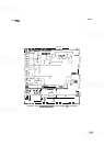
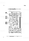
THIRD CONVERTER ASSEMBLY A10, CIRCUIT DESCRIPTION
The Third Converter Assembly A10 contains a 321.4 MHz amplifier followed by a 321.4 MHz bandpass filter, a
double balanced mixer, a 21.4 MHz IF preamplifier, a flatness compensation amplifier, and a band conversion
loss compensating amplifier. Also included in the Third Converter Assembly A10 are the 35 MHz calibration
oscillator and the 300 MHz third local oscillator. The 321.4 MHz signal from the Second Converter Assembly
A5 is amplified in the 321.4 MHz amplifier and filtered in the 321.4 MHz
bandpass filter before being mixed
with the 300 MHz oscillator in the balanced mixer. The output of the mixer is the difference frequency, 21.4
MHz, which is applied to the
IF
preamplifier where gain is added for the reference level calibration. The signal
now passes through two amplifiers to compensate for flatness across the bands and the varying conversion loss
of the bands before leaving the Third Converter Assembly A10 at a power level of approximately
0 dBm.
321.4 MHz Amplifier (A)
The 321.4 MHz Amplifier provides a broad
-
band fixed gain of approximately 18 dB to the incoming 321.4
MHz IF signal. The amplifier is a single
-
stage common
-
emitter transistor amplifier whose gain is determined by
the high frequency characteristics of
Q10, the input matching bandpass filter, and the output matching elements
L3 and
C8. The 3 dB bandwidth of the input bandpass filter is approximately 500 MHz (with 150 MHz and 650
MHz as the 3 dB points). The filter comprises series capacitor
C1, two shunt capacitors, C2, and C3, and series
inductors
L1 and L2. This bandpass filter attenuates the first and second LO feedthrough to prevent overload
-
ing of the amplifier and to minimize spurious responses. Bias to RF amplifier transistor Q10 is provided by Q9
and R3 through L25. Note that Q9 and associated components are RF decoupled by C6 and C7.
321.4 MHz Bandpass Filter (C)
The 321.4 MHz Bandpass Filter rejects the image frequency from the Second Converter Assembly A5 and limits
the signal power applied to the mixer in the Third Converter Assembly
A10 to a
3
dB bandwidth of about 9
MHz. The filter consists of four LC resonators that are tap
-
coupled at the input and output of the filter and
capacitively coupled between sections by traces on the printed circuit board. The center frequencies of the four
poles are adjusted by C9,
C10, C11, and C12.
300 MHz Oscillator
(D)
Transistor Ql and associated circuitry form
a
grounded
-
base Colpitts oscillator. Direct collector current for Q1
is supplied through L8, whose internal parallel capacitance causes it to self
-
resonate at 300 MHz. Inductor L12
and capacitors C15, C16, and C17, form a tank circuit that feeds back the collector current of
Q1 to its emitter.
The frequency of the tank circuit is selected by tuning L12. Power is tapped out of the tank circuit through C18
and
L11 and sent to 42, a buffer amplifier that distributes the power and provides a constant load to the
oscillator.
The 300 MHz buffer amplifier isolates the oscillator from the mixer and provides the high
-
level signal required
to drive the mixer. The buffer amplifier is a common
-
emitter amplifier in which R10 and R11 set the emitter
current. Base current is supplied, through self
-
resonant L9, from R5 and R6. Inductor L13 and capacitor C19
form a matching network that matches the impedance of the signal applied to the mixer's
(Ul) LO input. A test
port is provided, through R4 and
J1, to monitor frequency and amplitude of the 300 MHz Oscillator (Third
LO). Voltage regulator U2 and its associated circuitry provide a regulated power supply for
Q1 and
42.
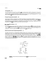
Double Balanced Mixer
(E)
The Double Balanced Mixer (Ul) mixes the 321.4 MHz second
IF
from the 321.4 MHz Amplifier with the 300
MHz Oscillator. This produces the sum and difference frequencies, 621.4 MHz and 21.4 MHz, that are sent to
the
IF
Preamplifier. The 621.4 MHz mixing product is removed by the matching filter at the input of the IF
Preamplifier. Inherent in the double balanced mixer is excellent port
-
to
-
port isolation.